Motor drive apparatus

a motor drive and motor technology, applied in the direction of electric generator control, dynamo-electric converter control, dynamo-electric gear control, etc., can solve the problems of excessive electric power being brought from the asynchronous machine to the battery, and excessive electric power being taken from the battery to the asynchronous machin

Active Publication Date: 2007-05-17
DENSO CORP
View PDF8 Cites 14 Cited by
  • Summary
  • Abstract
  • Description
  • Claims
  • Application Information

AI Technical Summary

Benefits of technology

[0038] As seen from the above, the present invention can prevent e...

Problems solved by technology

The conventional power-supply system apparatus, however, has a problem that, in the case where a voltage step-up operation for stepping up a DC voltage from the battery and a drive operation for driving the asynchronous machine as a starter are carried out at the same timing, excessive electric power is taken from the battery to the asynchro...

Method used


Image

  • Motor drive apparatus
  • Motor drive apparatus
  • Motor drive apparatus

Examples


first embodiment

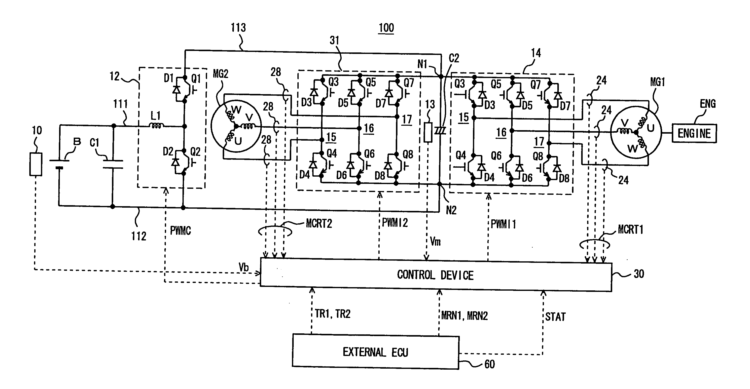
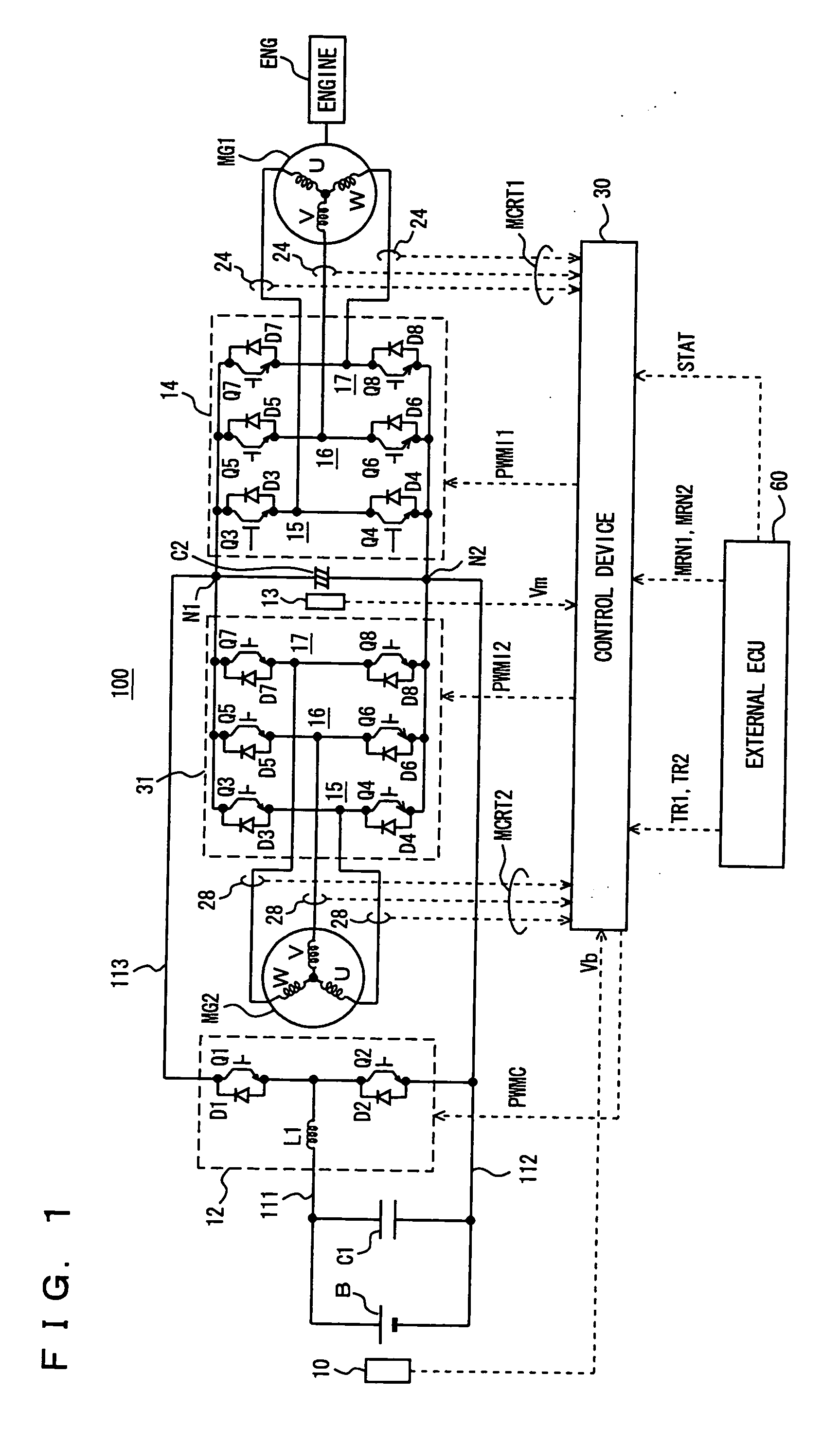
[0059]FIG. 1 is a schematic diagram of a motor drive apparatus according to a first embodiment of the present invention. Referring to FIG. 1, motor drive apparatus 100 in the first embodiment of the present invention includes a battery B, capacitors C1, C2, voltage sensors 10, 13, a voltage step-up converter 12, inverters 14, 31, current sensors 24, 28, and a control device 30.

[0060] A motor generator MG 1 is coupled to an engine ENG mounted on a hybrid vehicle. Motor generator MG1 functions as an electric generator that generates an AC voltage from a rotational force from engine ENG and also functions as an electric motor that starts engine ENG. Further, a motor generator MG2 is a drive motor for generating torque for driving drive wheels of the hybrid vehicle.

[0061] Battery B is connected between a power supply line 111 and a negative bus 112 of inverters 14, 31. Capacitor C1 is connected between power supply line 111 and negative bus 112 and in parallel with battery B. Capacito...

second embodiment

[0152] As described above in connection with the first embodiment, in motor drive apparatus 100 in FIG. 1, two motor generators MG1, MG2 each function as an electric generator generating an AC voltage in regenerative mode and function as an electric motor in powering mode for driving engine ENG or the drive wheels, depending on the running state of the vehicle.

[0153] Regarding the power balance of motor drive apparatus 100 as a whole, supposing that the power consumed by one motor generator (one of MG1 and MG2) driven in powering mode is represented by Pm, the power generated by the other motor generator driven in regenerative mode is represented by Pg, and the power input / output to / from capacitor C2 is represented by Pc, power balance P can be represented by expression (1):

P=Pm+Pg+Lg+Lm+Pc   (1)

where Lg, Lm represent respective power losses of the motor generators.

[0154] As clearly seen from expression (1), as long as power balance P is “0,” namely there is a balance between t...

third embodiment

[0200] According to the above-described first and second embodiments, when engine ENG is started, the timing at which the power required for voltage step-up by voltage step-up converter 12 is the maximum and the timing at which the power required for driving motor generator MG1 is the maximum are set at different timings and thus excessive electric power can be prevented from being taken from battery B.

[0201] Here, battery B has its battery output that considerably decreases when battery temperature BT is relatively low or relatively high as described in connection with the second embodiment. For example, as seen from FIG. 13, in the low-temperature region where battery temperature BT is lower than T2 and the high-temperature region where battery temperature BT is higher than T5, respective magnitudes of battery input Win and battery output Wout considerably decrease with respect to a predetermined electric power level in the region between T3 and T4. Thus, when battery temperature...


PUM


Abstract

A control device (30) generates, upon receiving an instruction to start engine (ENG) while drive wheels of a hybrid vehicle are driven by a motor generator (MG2), a signal (PWMC) to output the signal to a voltage step-up converter (12), and thereby drives and controls the voltage step-up converter (12) to step up a DC voltage (Vb) that is output from a battery (B) to a maximum voltage (Vmax) of a motor drive apparatus (100). Then, the control device (30) generates, when an output voltage (Vm) of the voltage step-up converter (12) reaches the maximum voltage (Vmax), a signal (PWMI1) to output the generated signal to an inverter (14). Accordingly, the inverter (14) is driven and controlled to drive motor generator (MG1) in powering mode.

Description

TECHNICAL FIELD [0001] The present invention relates to a motor drive apparatus, and particularly to a motor drive apparatus capable of preventing input / output of excessive electric power to / from a power supply that outputs a power supply voltage. BACKGROUND ART [0002] Japanese Patent No. 2834465 discloses a power-supply system apparatus for vehicles. This power-supply system apparatus includes a pulse inverter, a bidirectional converter and a battery. The bidirectional converter is connected between the battery and the pulse inverter, steps up a voltage from the battery to supply the resultant voltage to the pulse inverter, and steps down a voltage from the pulse inverter to supply the resultant voltage to the battery. [0003] The pulse inverter uses the voltage supplied from the bidirectional converter to drive an asynchronous machine. The asynchronous machine is used as an electric generator or starter. [0004] Thus, when the asynchronous machine is used as an electric generator, t...

Claims


Application Information

Patent Timeline
IPC IPC(8): H02P27/04B60L11/18B60L50/13B60L50/16H02P21/34H02P21/36H02P23/20H02P25/022H02P27/06
CPCB60L11/08B60L11/1803B60L11/1851B60L2210/14Y02T10/70Y02T10/705Y02T10/7077Y02T10/7225Y02T10/7005B60L50/13B60L50/51B60L58/10Y02T10/7072Y02T10/72H02P21/00H02P27/06
Inventor YAGUCHI, HIDEAKI
Owner DENSO CORP
Why Eureka
Try Eureka