Differential amplifier, differential amplifying method, and phase locked loop and delay locked loop using the same

a technology of differential amplifying and differential amplifiers, applied in pulse manipulation, pulse technique, instruments, etc., can solve the problems of increasing the load of the vco and increasing the power consumption of the interpolation circui

Active Publication Date: 2007-05-17
SAMSUNG ELECTRONICS CO LTD
View PDF6 Cites 16 Cited by
  • Summary
  • Abstract
  • Description
  • Claims
  • Application Information

AI Technical Summary

Benefits of technology

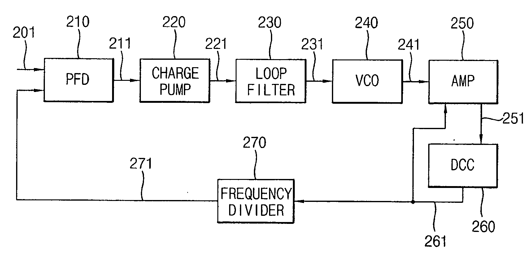
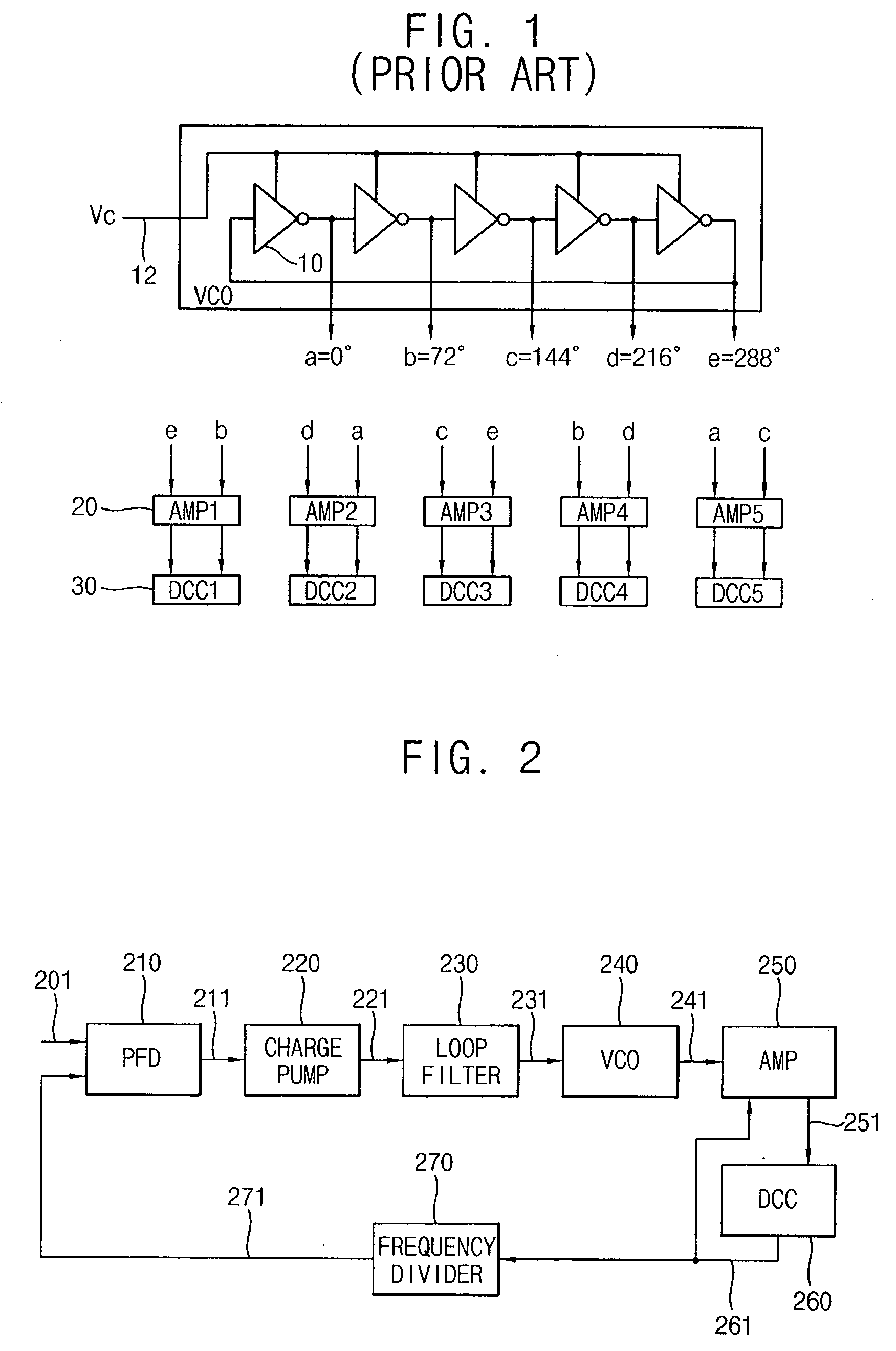
[0036] In accordance with still another aspect of the present invention, provided is a differential amplifying method that can include: receiving a first phase signal and at least two phase signals among a set of odd-numbered phase signals, wherein an average of phases of the at least two phase signals has a phase difference of substantially 180 degrees from the first phase signal; outputting a differentially amplified

Problems solved by technology

In addition, when using a phase interpolation circuit to provide differential signals having a phase difference of 180 degrees using odd-number

Method used


Image

  • Differential amplifier, differential amplifying method, and phase locked loop and delay locked loop using the same
  • Differential amplifier, differential amplifying method, and phase locked loop and delay locked loop using the same
  • Differential amplifier, differential amplifying method, and phase locked loop and delay locked loop using the same

Examples


Embodiment Construction

[0057] Hereinafter, illustrative embodiments in accordance with various aspects of the present invention are discribeded with reference to the accompanying drawings, wherein like elements are given like reference numerals.

[0058] It will be understood that, although the terms first, second, etc. can be used herein to describe various elements, these elements should not be limited by these terms. These terms are only used to distinguish one element from another. For example, a first element could be termed a second element, and, similarly, a second element could be termed a first element, without departing from the scope of the present invention. As used herein, the term “and / or” includes any and all combinations of one or more of the associated listed items.

[0059] It will be understood that when an element is referred to as being “on,”“connected” or “coupled” to another element, it can, be directly on, connected or coupled to the other element or intervening elements can be present...


PUM


Abstract

A differential amplifier includes an input stage, a biasing unit and a load unit. The input stage receives a first phase signal and at least two phase signals among odd-numbered phase signals, wherein an average of phases of the at least two phase signals has a phase difference of substantially 180 degrees from the first phase signal. The biasing unit is coupled between the input stage and a first power voltage. The load unit is coupled between the input stage and a second power voltage, and configured to output a differential output signal based on differentially amplifying of the first phase signal and the at least two phase signals. Therefore, a duty cycle distortion in an output signal of a duty cycle correction circuit can be prevented.

Description

CROSS-REFERENCE TO RELATED APPLICATIONS [0001] This application claims priority under 35 USC §119 to Korean Patent Application No. 10-2005-0108576, filed on Nov. 14, 2005, in the Korean Intellectual Property Office, the contents of which are herein incorporated by reference in its entirety. BACKGROUND OF THE INVENTION [0002] 1. Field of the Invention [0003] The present invention relates to a differential amplifier used in a phase locked loop (PLL) and a delay locked loop (DLL). [0004] 2. Description of the Related Art [0005] In a phase locked loop (PLL), a complementary metal oxide silicon (CMOS) differential amplifier is used to convert a small signal outputted from a voltage controlled oscillator (VCO) to a signal having a level used in a CMOS circuit. The CMOS differential amplifier receives a differential input signal having a phase difference of 180 degrees. [0006] Two phase signals are selected among a plurality of phase signals outputted from the voltage-controlled oscillator...

Claims


Application Information

Patent Timeline
IPC IPC(8): H03B27/00
CPCH03F3/45183H03F2203/45371H03K5/1565H03K2005/00052H03L7/08H03L7/0812H03L7/0996H03L7/0816H03F3/45
Inventor KIM, JIN-YOUNGKIM, KYU-HYOUN
Owner SAMSUNG ELECTRONICS CO LTD
Why Eureka
Try Eureka