Method and system for distance determination of rf tags

a distance determination and tag technology, applied in the field of distance determination of rf tags, can solve the problems of increasing the required time, unauthorized individuals may be opened, and all the collision overcoming methods are time-consuming, so as to achieve convenient implementation, improve accuracy, and reduce time-consuming

Active Publication Date: 2007-05-17
ZEBRA ENTERPRISE SOLUTIONS
View PDF18 Cites 112 Cited by
  • Summary
  • Abstract
  • Description
  • Claims
  • Application Information

AI Technical Summary

Benefits of technology

[0026] The present invention for distance determination of RF tags successfully address limitations of presently known methods by providing a simpler, more rapid, and therefore, more cost effective system, than currently used techniques for distance determination and discrimination of RF tags according to their distance from the reader. The method of the present invention is readily implemented using one channel or a plurality of channels, and at least one reader.

Problems solved by technology

The most significant limitation of each of the just described collision overcoming methods of U.S. Pat. Nos. 5,777,561, 6,265,962 and 6,377,203, is that all of these collision overcoming methods are time consuming.
Moreover, the required time greatly increases with the number of tags participating in the collision.
For example, the identification of the tag may be required in order to open a door to an access-limited area If a tag remote from the reader is identified by the reader, the door may be opened to an unauthorized individual.
This, however, may cause some tags not to be identified due to their orientation and / or interference.
However, the just described method suggesting using a separate position detector to detect the position of the tag identified by the reader is notably limited because it adds to the cost and complexity of the RFID system.
In addition, the position detection is performed after the tags are identified in a separate stage, which adds to the time required for the system operation.
However, position detection systems, such as described in U.S. Pat. No. 5,977,913, are complex and generally require a plurality of readers in different locations.
The use of power thresholds is inaccurate, as the power may depend on the orientation of the tag and / or on obstructions between the tag and the reader.
In addition, the system of U.S. Pat. No. 6,362,738 does not disclose a solution for resolving collisions when a plurality of tags respond together.

Method used


Image

  • Method and system for distance determination of rf tags
  • Method and system for distance determination of rf tags
  • Method and system for distance determination of rf tags

Examples


Embodiment Construction

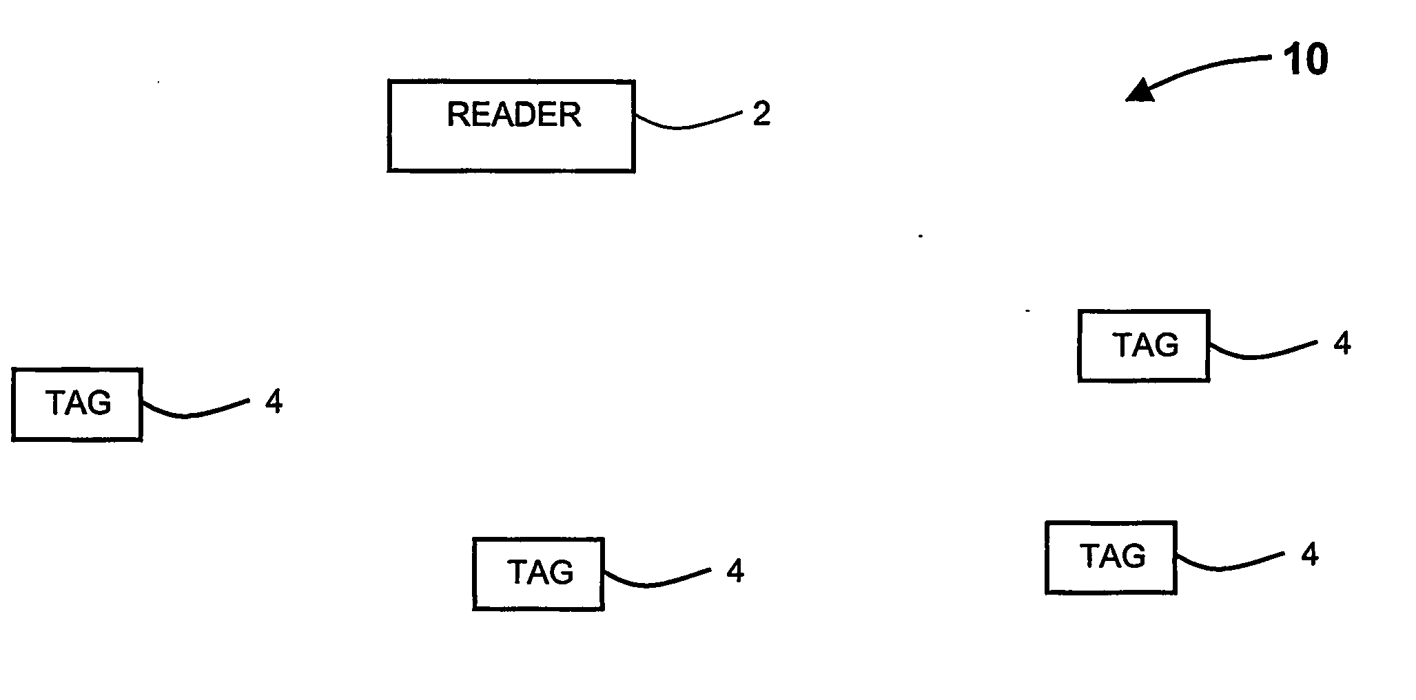
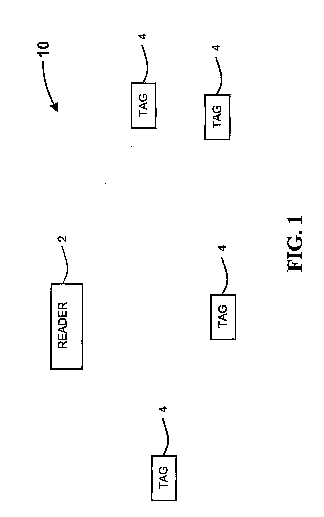
[0034] The present invention relates to distance determination of RF tags, used in RF identification systems, and more particularly, to a method and system for distance determination of RF tags and its applications, based on measuring the round trip delay by using one or more channels.

[0035] Hereinafter, the term ‘channel’ refers to an allocation of resources providing a link between a transmitter and a receiver. Exemplary channels are frequency band, time slot, space direction and spreading code.

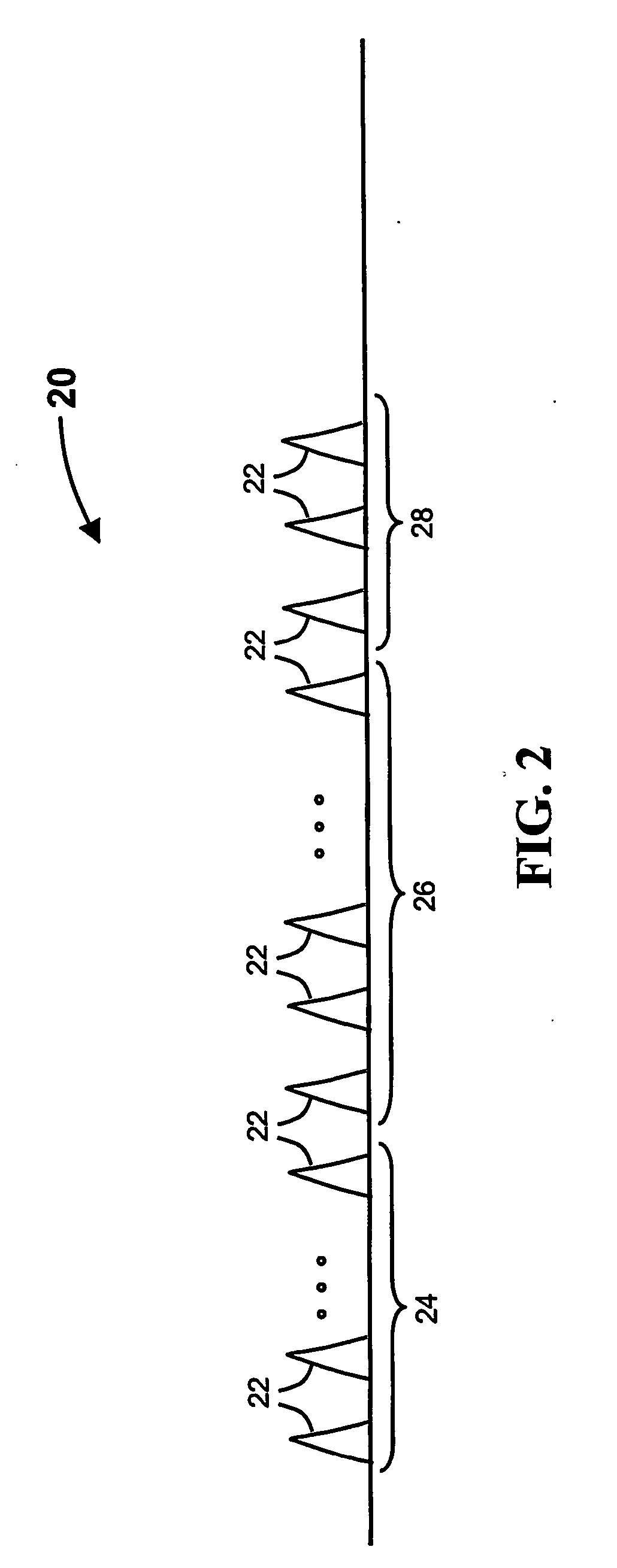
[0036] Hereinafter, the term ‘wide band signals’ or the equivalent term ‘spread spectrum signals’ refers to any spread spectrum signals types such as: direct sequence (DS), frequency-hopping (FH), multi-carrier CDMA, chirp signals, short or long pulses of any shape with or without time hopping.

[0037] Hereinafter, the term “reader cell” refers to a predetermined bounded volume, such as the volume bounded within a specified radius or between two radii. The accuracy of the bounds of the bou...


PUM


Abstract

The present invention relates to a method and system (10) for distance determination of RF tags (4) and its applications based on measuring the round trip delay, avoiding deterministic collisions between a plurality of wide band response signals transmitted by the tags (4) by adding a pseudo-random time delay to the wide band response signal, and iteratively reducing the collision probability between plurality of wide band response signals.

Description

FIELD AND BACKGROUND OF THE INVENTION [0001] The present invention relates to distance determination of RF tags, used in RF identification systems, and more particularly, to a method and system for distance determination of RF tags and its applications, based on measuring the round trip delay. [0002] RF identification (RFID) systems are used to track objects, animals and / or people in a large range of applications. RFID systems are radio communication systems that communicate between a radio transceiver, called a reader, and a number of inexpensive devices called Tags. An RFID system generally includes a plurality of tags which are attached to objects being monitored and one or more readers which are used to communicate with the tags. An encoder is optionally used to program the tags with unique identification information. [0003] One of the tasks commonly performed in RFID systems is determining which tags are located in the vicinity of a reader. For example, the reader may be locate...

Claims


Application Information

Patent Timeline
Patent Type & Authority Applications(United States)
IPC IPC(8): H04Q5/22G06K7/00H04B1/69H04L12/56
CPCG07C9/00111H04B1/69H04W64/00H04W74/08G01S13/758G06K7/0008G06K7/10029G06K7/10079G06K7/10306G07C9/28
Inventor RAPHAELI, RUTHRAPHAELI, DAN
Owner ZEBRA ENTERPRISE SOLUTIONS
Why Eureka
Try Eureka