
Accident Avoidance Systems and Methods

a technology of accident avoidance and system training, applied in the field of vehicle safety systems, can solve the problems of insufficient complexity or imprecise data on which the system is trained, and different views of data, so as to achieve the effect of preventing accidents

Inactive Publication Date: 2007-05-17
AMERICAN VEHICULAR SCI
View PDF20 Cites 169 Cited by
  • Summary
  • Abstract
  • Description
  • Claims
  • Application Information

AI Technical Summary

Benefits of technology

[0045] A method for preventing accidents between first and second vehicles at intersections in accordance with the invention includes determining the absolute position and velocity of the first vehicle, storing data in a memory unit relating to travel lanes, determining the absolute position and velocity of the second vehicle, predicting a collision between the first and second vehicles based on the position and velocity of the first and second vehicles and the travel lane data, and initiating an action or changing operation by a reactive component or system in the first vehicle when a collision is predicted.
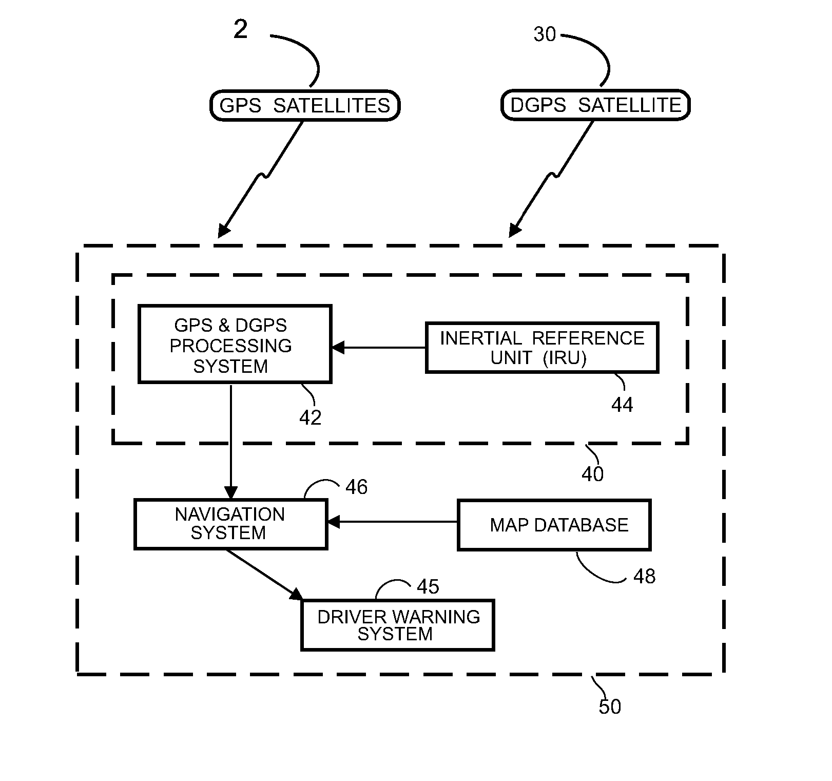
[0056] The above and other objects are achieved in the present invention which provides motor vehicle collision avoidance, warning and control systems and methods using GPS satellite location systems augmented with Precise Positioning Systems to provide centimeter location accuracy, and to derive vehicle attitude and position coordinates and vehicle kinematic tracking information. GPS location and computing systems being integrated with vehicle video scanning, radar, laser radar, terahertz radar and onboard speedometer and / or accelerometers and gyroscopes to provide accurate vehicle location information together with information concerning hazards and / or objects that represent impending collision situations for each vehicle. Advanced image processing techniques are used to quantify video information signals and to derive vehicle warning and control signals based upon detected hazards.
[0057] Outputs from multiple sensors as described above are used in onboard vehicle neural network and neural-fuzzy system computing algorithms to derive optimum vehicle warning and control signals designed to avoid vehicle collisions with other vehicles or with other objects or hazards that may be present on given roadways. In a preferred embodiment, neural fuzzy control algorithms are used to develop coordinated braking, acceleration and steering control signals to control individual vehicles, or the individual wheels of such vehicles, in an optimal manner to avoid or minimize the effects of potential collisions. Video, radar, laser radar, terahertz radar and GPS position and trajectory information are made available to each individual vehicle describing the movement of that vehicle and other vehicles in the immediate vicinity of that vehicle.

Problems solved by technology

Sometimes the data upon which the system is trained is sufficiently complex or imprecise that different views of the data will give different results.

Method used


Image

  • Accident Avoidance Systems and Methods
  • Accident Avoidance Systems and Methods
  • Accident Avoidance Systems and Methods

Examples


Embodiment Construction

1. Vehicle Collision Warning and Control

[0093] According to U.S. Pat. No. 5,506,584, the stated goals of the US DOT IVHS system are:

[0094] improving the safety of surface transportation

[0095] increasing the capacity and operational efficiency of the surface transportation system

[0096] enhancing personal mobility and the convenience and comfort of the surface transportation system

[0097] reducing the environmental and energy impacts of the surface transportation system

[0098] The RtZF™ system in accordance with the present invention satisfies all of these goals at a small fraction of the cost of prior art systems. The safety benefits have been discussed above. The capacity increase is achieved by confining vehicles to corridors where they are then permitted to travel at higher speeds. This can be achieved immediately where carrier phase DGPS is available or with the implementation of the highway-located precise location systems as shown in FIG. 11. An improvement is to add the c...


PUM


Abstract

Method and system for preventing accidents between first and second vehicles includes a positioning system arranged in each vehicle for determining the absolute position thereof, a memory unit arranged in the first vehicle for storing data about travel lanes, a communication system for transmitting the position of the second vehicle to the first vehicle, a receiver system arranged in the first vehicle for receiving position information from the second vehicle, a processor coupled to the positioning system, the receiver system and the memory unit in the first vehicle for predicting a collision between the vehicles based on the position of the vehicles and travel lane data, and a reactive component arranged in the first vehicle and coupled to the processor. The reactive component is arranged to initiate an action or change its operation when a collision is predicted by the processor, e.g., sound or indicate an alarm.

Description

[0001] This application is: [0002] 1. a continuation-in-part (CIP) of U.S. patent application Ser. No. 11 / 034,325 filed Jan. 12, 2005 which is a CIP of U.S. patent application Ser. No. 10 / 822,445 filed Apr. 12, 2004, now U.S. Pat. No. 7,085,637, which is: [0003] A) a CIP of U.S. patent application Ser. No. 10 / 118,858 filed Apr. 9, 2002, now U.S. Pat. No. 6,720,920, which is: [0004] 1) a CIP of U.S. patent application Ser. No. 09 / 177,041 filed Oct. 22, 1998, now U.S. Pat. No. 6,370,475, which claims priority under 35 U.S.C. §119(e) of U.S. provisional patent application Ser. No. 60 / 062,729 filed Oct. 22, 1997; [0005] 2) a CIP of U.S. patent application Ser. No. 09 / 679,317 filed Oct. 4, 2000, now U.S. Pat. No. 6,405,132, which is a CIP of U.S. patent application Ser. No. 09 / 523,559 filed Mar. 10, 2000, now abandoned, which claims priority under 35 U.S.C. §119(e) of U.S. provisional patent application Ser. No. 60 / 123,882 filed Mar. 11, 1999; and [0006] 3) a CIP of U.S. patent applicati...

Claims


Application Information

Patent Timeline
IPC IPC(8): B60Q1/00G01S19/48
CPCB60N2/2863B60W10/06B60W10/18B60W10/184B60W10/20B60W30/02B60W30/04B60W30/095B60W30/14B60W30/16B60W30/18154B60W30/18172B60W40/06B60W40/072B60W40/076B60W50/00B60W50/14B60W2050/0071B60W2050/0073B60W2050/0078B60W2050/046B60W2050/048B60W2420/40B60W2420/403B60W2420/52B60W2550/12B60W2550/20B60W2550/306B60W2550/402G01C21/26G01C21/30G01C21/3697G01S5/0072G01S13/931G01S17/023G01S17/89G01S19/17G01S19/41G01S19/42G01S19/50G01S2013/9339G01S2013/9342G01S2013/9346G01S2013/935G01S2013/936G01S2205/002G05D1/0221G05D1/0225G05D1/0246G05D1/0257G05D1/027G05D1/0274G05D1/0278G05D2201/0213G06F17/30241G08G1/096783G08G1/16G08G1/161G08G1/163G08G1/164G01S13/865G01S13/867G01S2007/4975G01S2013/9321G01S2013/9332G01S2013/9353G01S2013/9357G01S2013/9375G01S2013/9378G01S2013/9382G08G1/165G08G1/166G08G1/167G06F16/29G01S2013/93273G01S2013/9329G01S2013/9318G01S2013/9319G01S2013/9322G01S2013/9315G01S2013/9316G01S2013/93185G01S2013/93272G01S2013/93271G01S2013/932G01S17/86B60W2554/4041B60W2554/00B60W2556/50B60W2555/20B60W2050/0075B60W2420/408B60W2554/4026B60W2554/4029B60W30/18159B60W2554/406
Inventor BREED, DAVID S.DUVALL, WILBUR E.JOHNSON, WENDELL C.
Owner AMERICAN VEHICULAR SCI
Learn More