Image sensor

a technology of image sensor and image, applied in the field of image sensor, can solve the problems of tainted values read for the last read pixels, long time necessary to read each line, and inability to take snapshots,

Inactive Publication Date: 2007-05-17
STMICROELECTRONICS SRL
View PDF7 Cites 11 Cited by
  • Summary
  • Abstract
  • Description
  • Claims
  • Application Information

AI Technical Summary

Benefits of technology

[0009] Another object of the present invention is to provide such an image sensor which enables taking snapshots with no degradation in the quality of the measured light signals.

Problems solved by technology

A disadvantage of the previously-described image sensor is that the time necessary to read each line is relatively long.
Further, this sensor is not provided to take snapshots.
Since the voltage “stored” on the comparator input tends to “deteriorate” relatively fast, the values read for the last read pixels would be tainted with error, given the long read time necessary to scan all of the pixels.

Method used


Image

  • Image sensor
  • Image sensor
  • Image sensor

Examples


Embodiment Construction

[0038] For clarity, the same elements have been designated with the same reference numerals in the different drawings.

[0039] In a first part, an image sensor according to the present invention and an image capture method according to the present invention will be described.

[0040] In a second part, a “wide dynamic range” image capture method enabling measurement of a very wide range of light intensity values will be described.

[0041] In a third part, a possible use of an example of a sensor according to the present invention enabling masking of the pixels of an image sensor according to the present invention will be described.

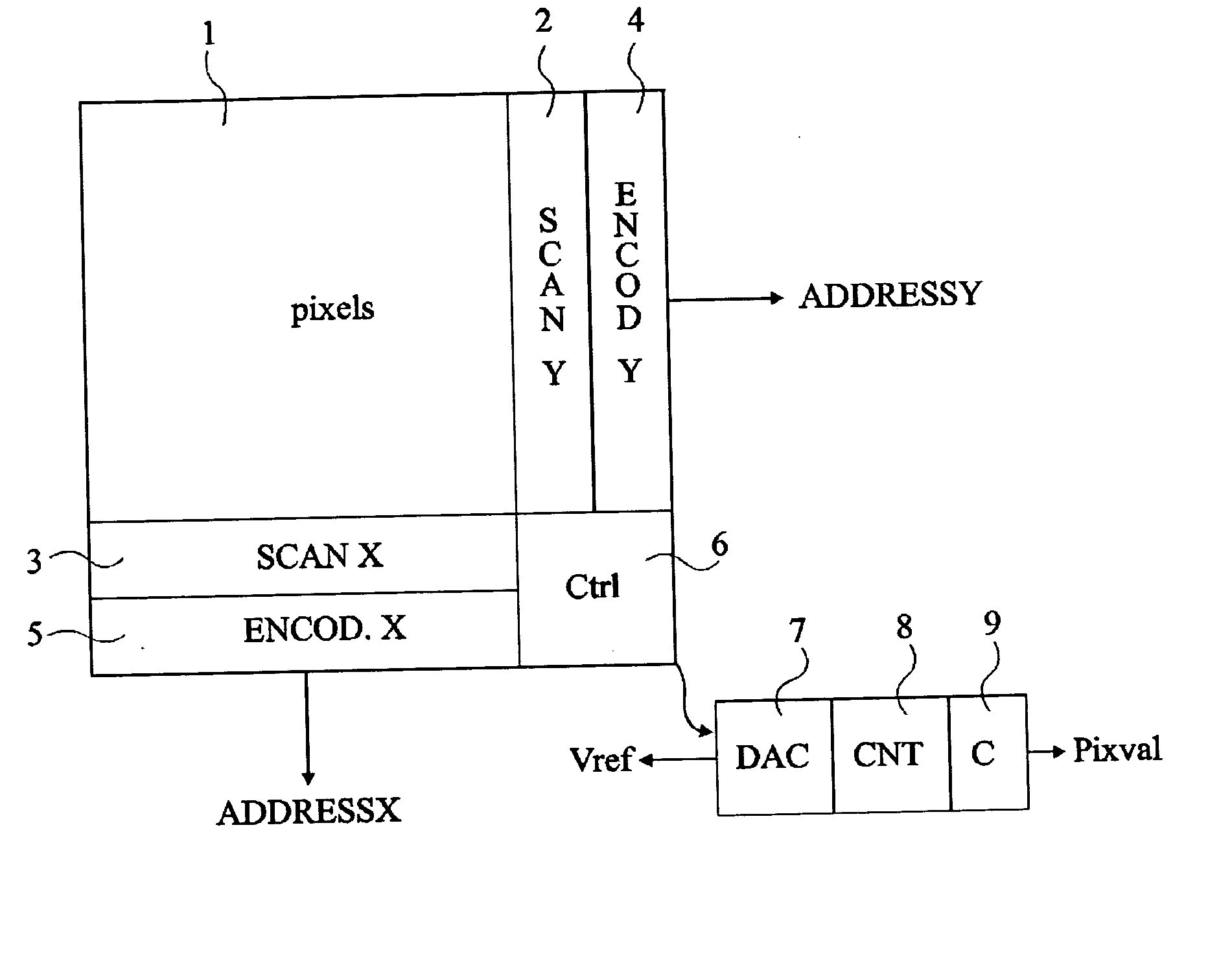
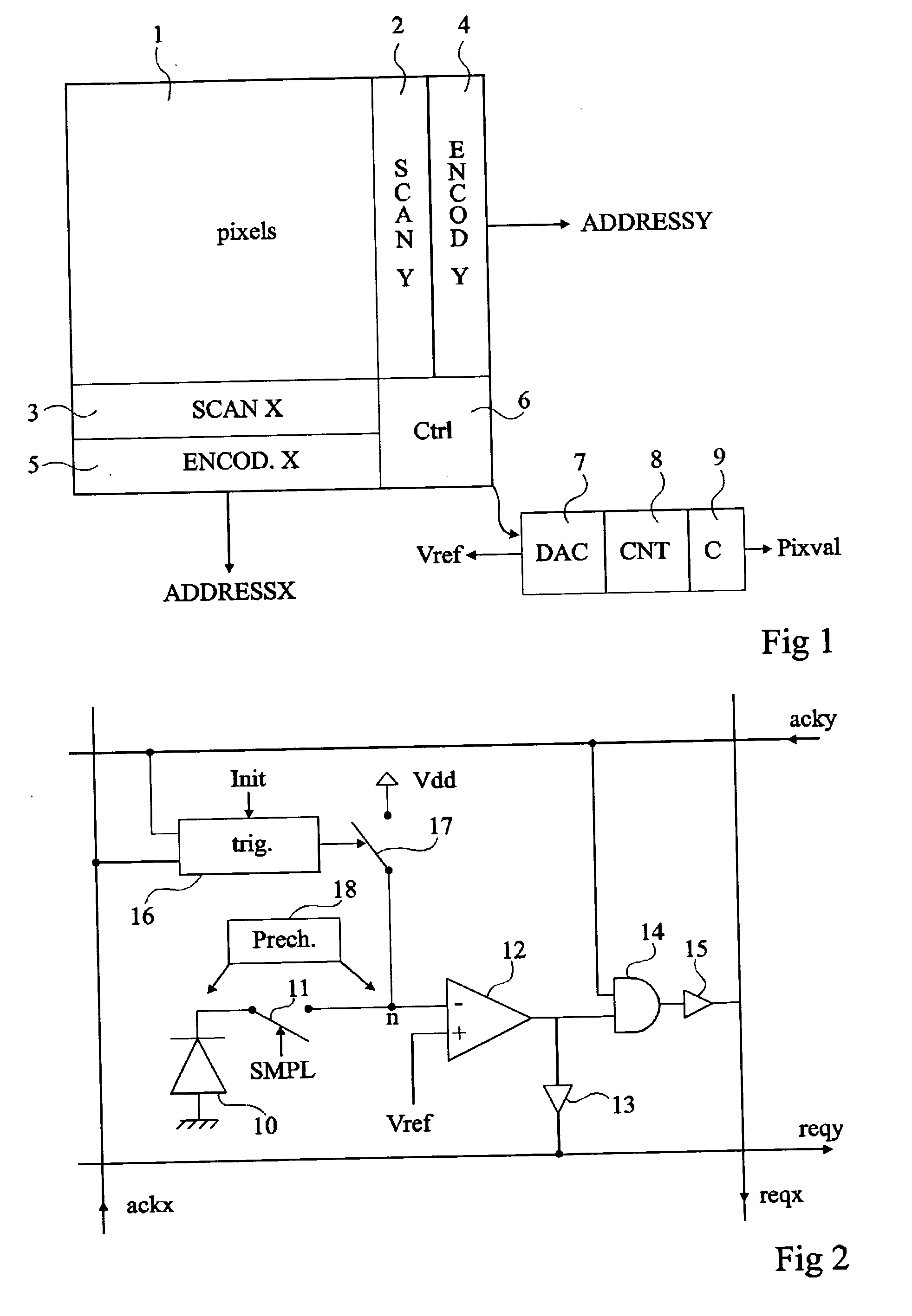
[0042] 1. Image Sensor

[0043] 1.1 General Considerations

[0044] An image sensor according to the present invention comprises a set of pixels. Each pixel comprises a photodetector such as a photodiode. The image sensor comprises detection means enabling, at a given time, detecting which pixels receive, in other words, record, a given light intensity value. The...


PUM


Abstract

An image sensor including an assembly of pixels each having a photodetector, and having circuitry for detecting, at a given time, pixels receiving a light intensity value substantially equal to a given value and coding circuitry providing an address for each of said pixels.

Description

BACKGROUND OF THE INVENTION [0001] 1. Field of the Invention [0002] The present invention relates to an image sensor, and more specifically to a camera-type sensor capable of providing a video signal, that is, the equivalent of an image sequence with a 25- or 30-Hz frequency corresponding to standard video signal frequencies. [0003] 2. Discussion of the Related Art [0004] An example of an image sensor is described in U.S. Pat. No. 6,271,785. As shown in FIG. 1 of this patent, the image sensor comprises an array of pixels arranged in rows and columns. Each pixel comprises a photodetector connected to an input of a comparator and a switch placed between the comparator output and a column line, the switch being controlled by a row line (ROW1, ROW2 . . . ). The output of a digital-to-analog converter (D / A) is connected to the second input of the comparator of each pixel. The D / A converter is controlled by a counter. Each column line is connected to a register. [0005] Conventionally, the...

Claims


Application Information

Patent Timeline
Patent Type & Authority Applications(United States)
IPC IPC(8): H04N5/335H04N5/374H04N5/376
CPCH04N3/155H04N25/40H04N25/772
Inventor PUCHADES, JOSEP SEGURA
Owner STMICROELECTRONICS SRL
Why Eureka
Try Eureka