Double jet film cooling structure

a cooling structure and film technology, applied in the direction of cooling/ventilation/heating modification, electrical equipment, machines/engines, etc., can solve the problem of low film efficiency and indicate the cooling and achieve the effect of effective cooling of the wall surface, suppressing the separation of cooling medium from the wall surface, and enhancing the film efficiency on the wall surfa

Active Publication Date: 2007-05-17
KAWASAKI HEAVY IND LTD
View PDF3 Cites 13 Cited by
  • Summary
  • Abstract
  • Description
  • Claims
  • Application Information

AI Technical Summary

Benefits of technology

[0007] Therefore, the present invention is intended to provide a film cooling structure for enhancing a film efficiency on a wall surface of, e.g., moving and static blades of a gas turbine so that the wall surface can be cooled efficiently.
[0009] According to the constitution aforementioned, the cooling media from the pair of jetting holes interfere with each other so that by the swirl flow of the cooling medium on one side, the cooling medium on the other side is pressed onto the wall surface. Thereby, the separation of the cooling medium from the wall surface is suppressed. Therefore, the film efficiency on the wall surface can be enhanced and the wall surface is cooled effectively.
[0010] Preferably, jetting speed vectors of the cooling media jetted from the pair of jetting holes respectively have transverse angle components β1 and β2 on a plane along the wall surface with respect to a flow direction of the high-temperature gas in the gas-flow passage, the transverse angle components β1 and β2 being different from each other. Therefore, the mutual interference effect of the cooling media can be obtained easily.
[0011] Preferably, the transverse angle components β1 and β2 are directed in opposite directions to each other with respect to the flow direction. By doing this, on the wall surface along the flow direction of high-temperature gas, the film flow of the cooling medium is formed effectively and the film efficiency is improved more.
[0012] Preferably, the transverse angle components β1 and β2 are 5 to 175°. Preferably, the jetting speed vectors respectively have longitudinal angle components α1 and α2 which are perpendicular to the wall surface, the longitudinal angle components α1 and α2 being 5 to 85°. Preferably, each of the pair of jetting holes has a hole diameter D, and the pair of jetting holes are positioned relative to each other with a transverse interval W in an perpendicular direction which is perpendicular to the flow direction and with a longitudinal interval L in the flow direction, the transverse interval W being 0 D to 4 D and the longitudinal interval L being 0 D to 8 D. Preferably, the transverse interval W is 0.5 D to 2 D and the longitudinal interval L is 1.5 D to 5 D. According to these preferred constitutions, strong swirls toward the wall surface are generated and the wall surface can be cooled more effectively.
[0013] According to the present invention mentioned above, the separation of the cooling medium on the wall surface exposed to high-temperature gas is suppressed, and a satisfactory film flow can be generated on the wall surface, thus the wall surface can be cooled efficiently.

Problems solved by technology

However, conventionally, the cooling medium jetted from the jetting holes into the passage of high-temperature gas is easily separated from the wall surface, so that the film efficiency indicating the cooling efficiency on the wall surface is low.

Method used


Image

  • Double jet film cooling structure
  • Double jet film cooling structure
  • Double jet film cooling structure

Examples


second embodiment

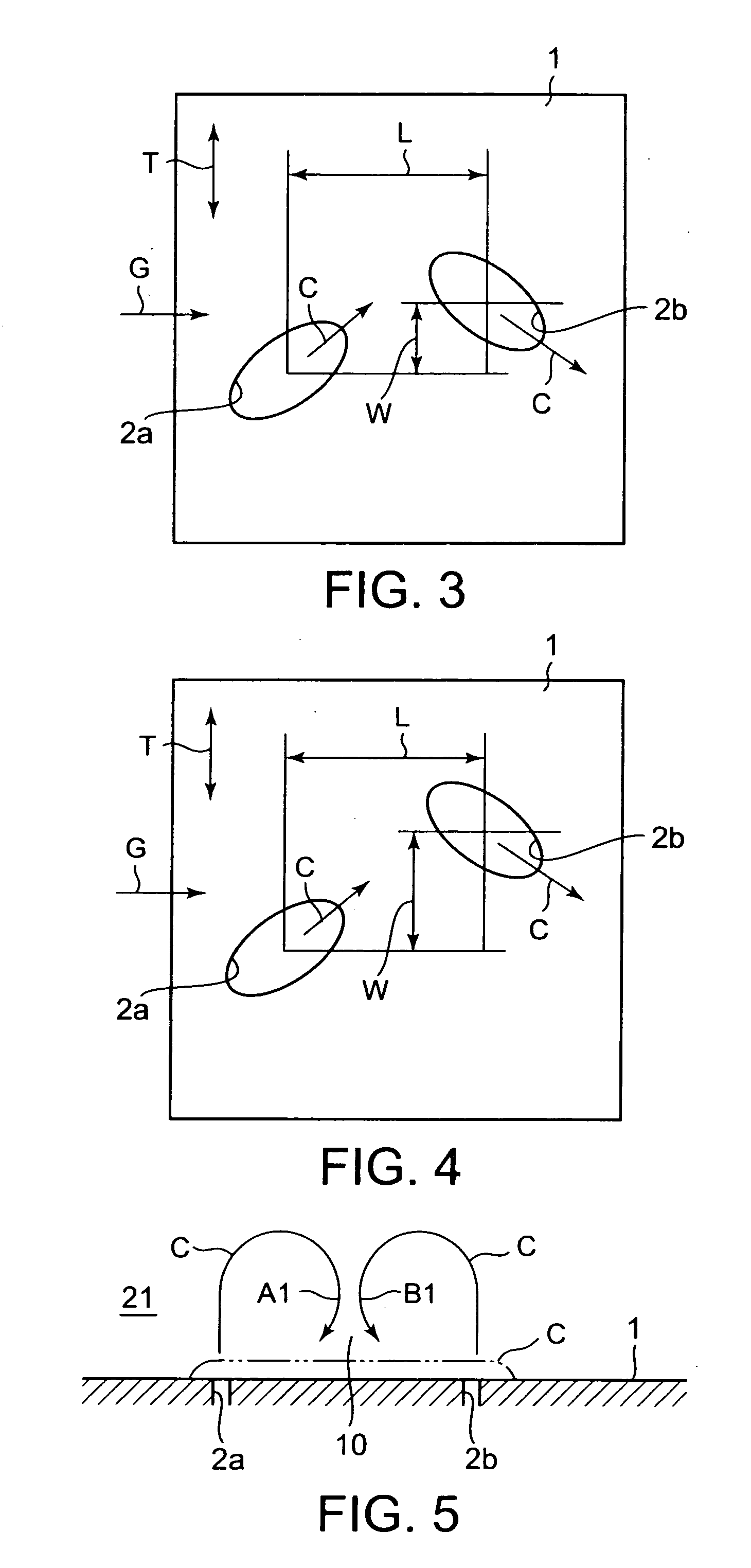
[0027] Further, in the second embodiment shown in FIG. 3, the transverse interval W is equal to 1 D, and the longitudinal interval L is equal to 3 D.

third embodiment

[0028] Moreover in the third embodiment shown in FIG. 4, the transverse interval W is equal to 2 D, and the longitudinal interval L is equal to 3 D.

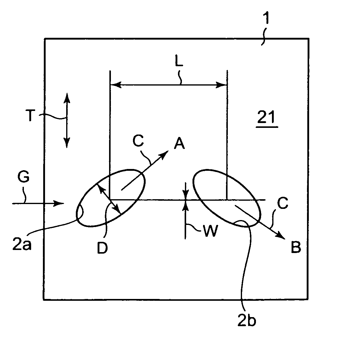
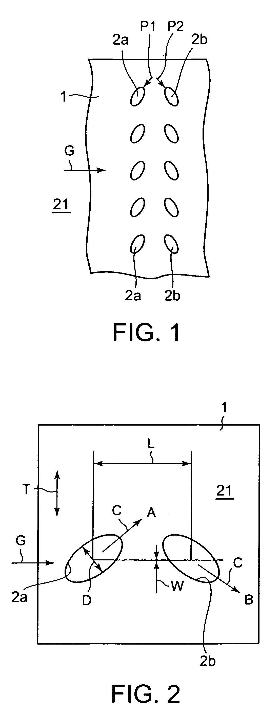
[0029] The cooling media C jetted from the respective paired jetting holes 2a and 2b shown in FIGS. 2 to 4 are mutually influenced and act so as to press the counterpart against the wall surface 1. The situation will be explained by referring to FIG. 5. FIG. 5 shows a section perpendicular to the flow direction of the high-temperature gas G. The two jetting holes 2a and 2b are adjacent to each other, and the jetting directions of the cooling media C from the two holes 2a and 2b are different from each other as viewed in the direction perpendicular to the wall surface 1. Therefore, a low-pressure portion 10 is generated between the two flows of the cooling media C. Thereby, on the inner sides of the cooling media C, i.e., in the portions opposite to each other, a flow toward the wall surface 1 is generated. By doing this, in the flows of ...


PUM


Abstract

A film cooling structure includes a wall surface which faces a gas-flow passage for high-temperature gas. One or more than one pair of jetting holes are formed on the wall surface so as to respectively jet cooling media into the gas-flow passage. The pair of jetting holes respectively have jetting directions in which the cooling media are jetted from the pair of jetting holes into the gas-flow passage. The jetting directions of the pair of jetting holes are respectively set so as to respectively form swirls in directions in which the cooling media are mutually pressed against the wall surface.

Description

CROSS REFERENCE TO RELATED APPLICATIONS [0001] This application is based upon the prior Japanese Patent Application No. 2005-332530 filed on Nov. 17, 2005, the entire contents of which are incorporated herein by reference. BACKGROUND OF THE INVENTION [0002] 1. Field of the Invention [0003] The present invention relates to a film cooling structure in which jetting holes are formed on a wall surface, which faces a passage of high-temperature gas, of such as moving blades, static blades, and an inner cylinder of a combustor of a gas turbine. A cooling medium jetted from the jetting holes flows along the wall surface so that the wall surface is cooled by the cooling medium. [0004] 2. Description of the Related Art [0005] Conventionally, on the wall surface of such as the moving blade of the gas turbine, many jetting holes pointing in the same direction are formed. By a film flow of a cooling medium like air jetted from these jetting holes, the wall surface aforementioned exposing to hig...

Claims


Application Information

Patent Timeline
Patent Type & Authority Applications(United States)
IPC IPC(8): H05K7/20
CPCF01D5/186F05D2260/202F05D2260/2214F05D2260/209
Inventor SUGIMOTO, TAKAOTANAKA, RYOZOTSUJI, KOICHIROBOHN, DIETERKUSTERER, KARSTEN
Owner KAWASAKI HEAVY IND LTD
Why Eureka
Try Eureka