Extended source laser illuminator

Active Publication Date: 2007-05-17
NORTHROP GRUMMAN SYST CORP
View PDF7 Cites 51 Cited by
  • Summary
  • Abstract
  • Description
  • Claims
  • Application Information

AI Technical Summary

Benefits of technology

[0004] An apparatus that provides a safer, high brightness glare source. The apparatus comprises a laser to emit a light beam, and a magnifying telescope, including a negative lens to expand the light beam and a positive lens to collimate the expanded li

Problems solved by technology

For example, laser illuminators provide an unequivocal warning to the adversary that his presence has been detected and may also impede mobility by degrading visual sensitivity.
Effectiveness of laser illuminators has been limited by the inability to project sufficient light at a distance (“downrange”) and, at the same tim

Method used


Image

  • Extended source laser illuminator
  • Extended source laser illuminator
  • Extended source laser illuminator

Examples


Example

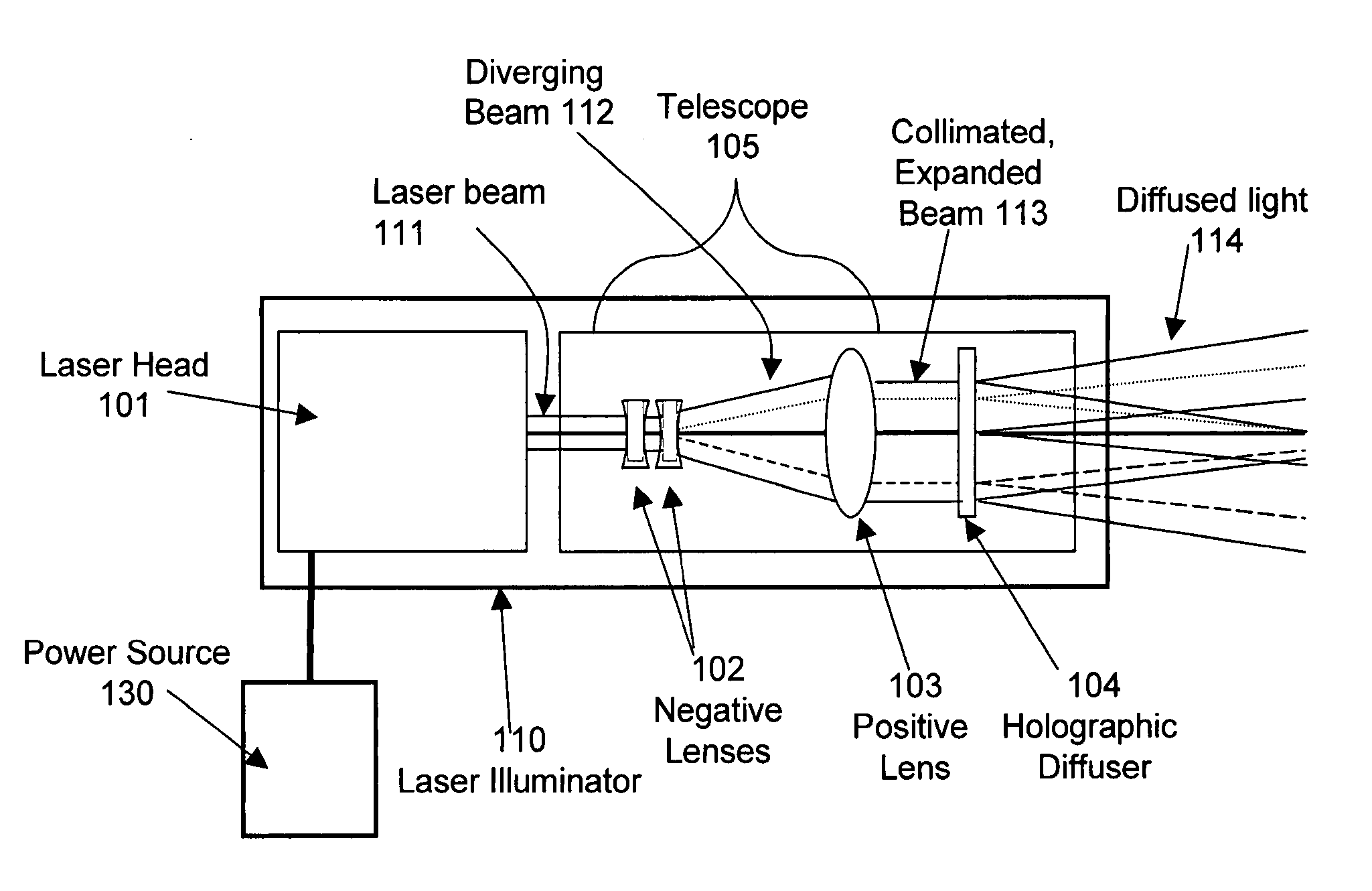
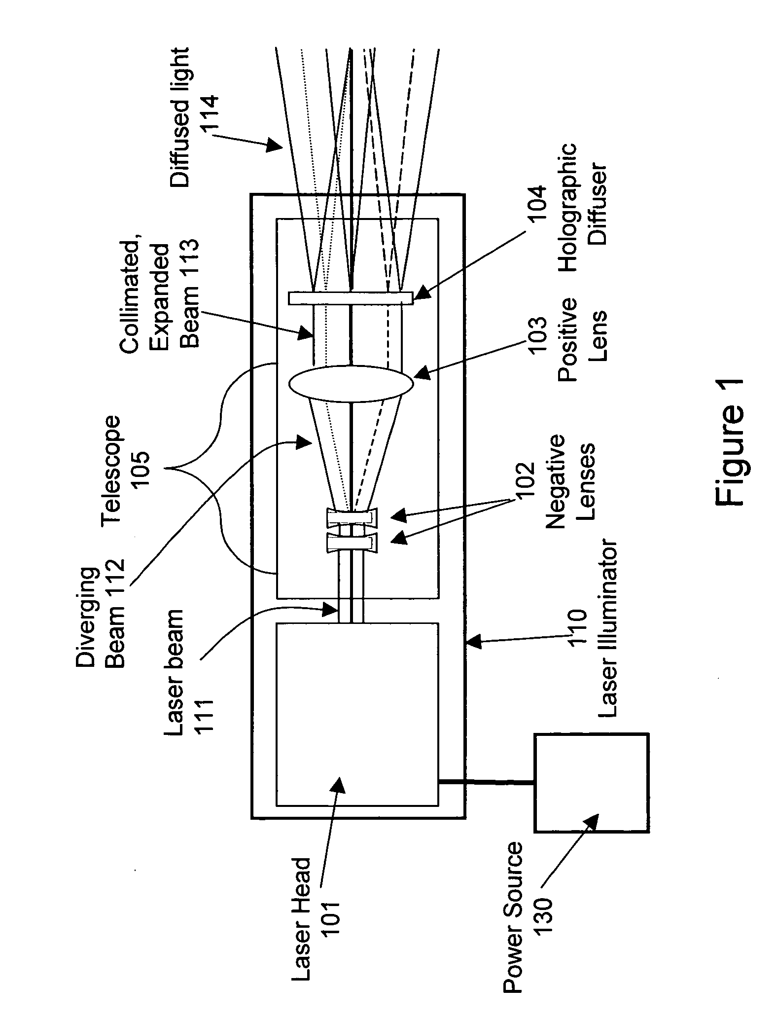
[0009] In accordance with an embodiment, the present invention provides a extended source laser illuminator which incorporates a diffuser that may increase the maximum permissible exposure at the aperture, thereby affording increased light transmission downrange as well as safer light exposure at close range. This invention relates to laser illuminators which can project sufficient light for a glare source at a distance (“downrange”) and, at the same time, be eye safe at close range.

[0010]FIG. 1 is diagrammatic representation of an extended source laser illuminator 110 in accordance with an embodiment of the present invention. As shown in FIG. 1, the laser illuminator 110 may include, for example, a laser head 101, a magnifying telescope 105 and a holographic optical element 104.

[0011] The laser illuminator 110 is powered by power source 130. The power source 130 may be located internal to or external to the illuminator 110. The power source 130 may be a battery power source which...


PUM


Abstract

An apparatus provides a safer, high brightness glare or illumination source. The apparatus comprises a laser to emit a light beam, and a magnifying telescope, including a negative lens to expand the light beam and a positive lens to collimate the expanded light beam. The apparatus also includes a holographic diffuser to receive the collimated light beam and to produce a diffused light beam. The diffused light beam has an extended cross section and provides an extended glare source at increased power down range.

Description

FIELD OF INVENTION [0001] The present invention relates to laser illuminators. In particular, the present invention provides an extended source laser illuminator. BACKGROUND OF THE INVENTION [0002] Lasers are used in a myriad of industrial, medical, commercial, scientific and military applications. The advent of compact, battery-powered solid-state lasers has led to an interest in developing light-based non-lethal technologies (NLT) for law enforcement and military applications. Laser illuminators, capable of producing non-damaging high-brightness glare sources have applications in suspect apprehension, crowd control, perimeter defense, and intruder delay and denial. For example, laser illuminators provide an unequivocal warning to the adversary that his presence has been detected and may also impede mobility by degrading visual sensitivity. Effectiveness of laser illuminators has been limited by the inability to project sufficient light at a distance (“downrange”) and, at the same ...

Claims


Application Information

Patent Timeline
IPC IPC(8): F21V23/02
CPCF21L4/005F21S48/10F21V5/008F21W2131/103F21Y2101/02F21Y2101/025F41G1/35F41H13/0056G02B5/02G02B5/32G02B27/0955G02B27/0972G02B27/30G02B19/0052G02B19/0014F21Y2115/10F21Y2115/30F21S41/14F21S41/16F21S41/25F21S41/28F21S41/285F21S41/00
Inventor KOSNIK, WILLIAM D.NOVAR, BRENDA J.VILLAVICENCIO, VICTOR I.
Owner NORTHROP GRUMMAN SYST CORP
Why Eureka
Try Eureka