Image forming apparatus

a technology of forming apparatus and forming tube, which is applied in the direction of electrographic process apparatus, instruments, optics, etc., can solve the problems of affecting the image, reducing the thickness of the toner layer, and affecting the image, so as to prevent the simultaneous fusing of toner and remove the effect of easy and reliable removal, preventing outflow and preventing the effect of outflow

Inactive Publication Date: 2007-05-17
SHARP KK
View PDF3 Cites 20 Cited by
  • Summary
  • Abstract
  • Description
  • Claims
  • Application Information

AI Technical Summary

Benefits of technology

[0018] Here, a rotation angle at a time of reverse rotation of a surface of the developer bearing member may be set within a range of approximately 7 to 23 degrees. By merely causing slight reverse rotation of the developer bearing member upon completion of operation in this way, toner that has adhered or stuck to the toner layer regulating blade can be easily and reliably removed.
[0019] It should be noted that in a development apparatus according to the present invention, two toner layer regulating blades may be provided, a first toner layer regulating blade provided at an upstream side of the rotation direction of the developer bearing member and a second toner layer regulating blade provided at a downstream side of the rotation direction. Fusing of toner occurs at both toner layer regulating blades, so the fusing of toner can be prevented simultaneously.
[0020] Furthermore, a toner scattering prevention sheet may be provided such that a tip end thereof contacts a surface of the photosensitive body, near an opening of a development tank that accommodates the developer bearing member. By providing the toner scattering prevention sheet, it is possible to prevent outflow and scattering of toner to the outside of the development tank due to reverse rotation. Furthermore, an optical component is preferably arranged near the photosensitive body and near the development tank. By providing the toner scattering prevention sheet, it is possible to prevent the optical component from becoming soiled by toner sputtering.
[0021] Here, a movement distance of the surface of the developer bearing member at a time of reverse rotation may be within a range from a position at a time of development stoppage to immediately prior to where the toner scattering prevention sheet that contacts the photosensitive body goes into a non-contact state with the photosensitive body. By keeping within this range, the toner scattering prevention sheet can always be maintained in a state of contact with the photosensitive body even when the developer bearing member rotates in reverse, and therefore it is possible to reliably prevent outflow and scattering of toner to the outside of the development tank.
[0022] Furthermore, in a state where the toner scattering prevention sheet is formed of an elastic material and a tip end thereof is arranged in a curved shape so as to press against a surface of the photosensitive body, a movement distance of the surface of the developer bearing member at a time of reverse rotation may be within a range in which a pressure contact line between the tip end of the toner scattering prevention sheet and the surface of the photosensitive body does not deviate even when a curvature direction of the toner scattering prevention sheet changes due to reverse rotation. By keeping within this range, the toner scattering prevention sheet can always be maintained in a state of contact with the photosensitive body even when the developer bearing member rotates in reverse, and therefore it is possible to prevent outflow and scattering of toner to the outside of the development tank.
[0023] Furthermore, in a state where the toner scattering prevention sheet is formed of an elastic material and a tip end thereof is arranged in a curved shape so as to press against a surface of the photosensitive body, when a line of intersection between a straight line joining a fixed end center of the toner scattering prevention sheet and a rotational center of the photosensitive body and the surface of the photosensitive body is set as a reference line, a movement distance of the surface of the developer bearing member at a time of reverse rotation may be within a range in which the tip end of the toner scattering prevention sheet does not exceed the reference line. By keeping within this range, the toner scattering prevention sheet does not undergo a change in its curvature direction even when the developer bearing member is rotated in reverse. When the curvature direction changes, there is a possibility that the tip end portion of the toner scattering prevention sheet will rebound due to its own elasticity, and when it rebounds there is a possibility that toner inside the development tank will outflow or scatter to the outside due to the force of the toner scattering prevention sheet, but since there is no change in the curvature direction of the toner scattering prevention sheet according to the present invention, this problem does not arise. That is, outflow and scattering of toner to the outside of the development tank can be reliably prevented.

Problems solved by technology

In the charging of the toner layer and formation of the thin layer, toner adhesion to the toner layer regulating blade is caused due to long use, such that a good toner layer cannot be formed and may lead to image deterioration.
At first the adhered substance merely extends as a thin film on the surface and is at a level that presents no particular problem to image formation, but this builds up due to prolonged use and eventually exerts an adverse effect on images.
That is, the chargeability of the toner is worsened by the toner layer regulating blade due to the adhered substance, and the adhered substance blocks the inflow opening for toner between the toner layer regulating blade and the development roller, or forms mechanical roughness on the surface contacting the development roller, which leads to overall or local reductions in the toner layer thickness and local slippage (layer thickness increases), such that a uniform toner layer cannot be formed.
However, with the development apparatus of patent document 1, since the angle for reverse rotation is as much as 150 degrees, there is a problem of outflow of toner from the development tank due to reverse rotation of the development roller.
Consequently, in the case of causing only the development roller to rotate in reverse while the photosensitive drum is stopped, there is a problem of unnecessary friction on the contact surface thereof.
Moreover, with the development apparatus of patent document 2, since the driving for the reverse rotation of the development roller continues for as long as one minute, there is a problem even more than with patent document 1 of outflow of toner from the development tank due to reverse rotation of the development roller.
However, no countermeasure whatsoever is conducted in regard to this in the development apparatus of patent document 2.
Furthermore, since the drive motor for the photosensitive drum is also turned on during reverse rotation of the development roller, reverse rotation is performed while the development roller and the photosensitive drum are in a state of contact, which presents a problem of unnecessary friction being caused at both contact surfaces.

Method used


Image

  • Image forming apparatus
  • Image forming apparatus
  • Image forming apparatus

Examples


Embodiment Construction

[0030] Hereinafter, an image forming apparatus provided with a development apparatus according to an embodiment of the present invention will be described with reference to the accompanying drawings.

[0031]

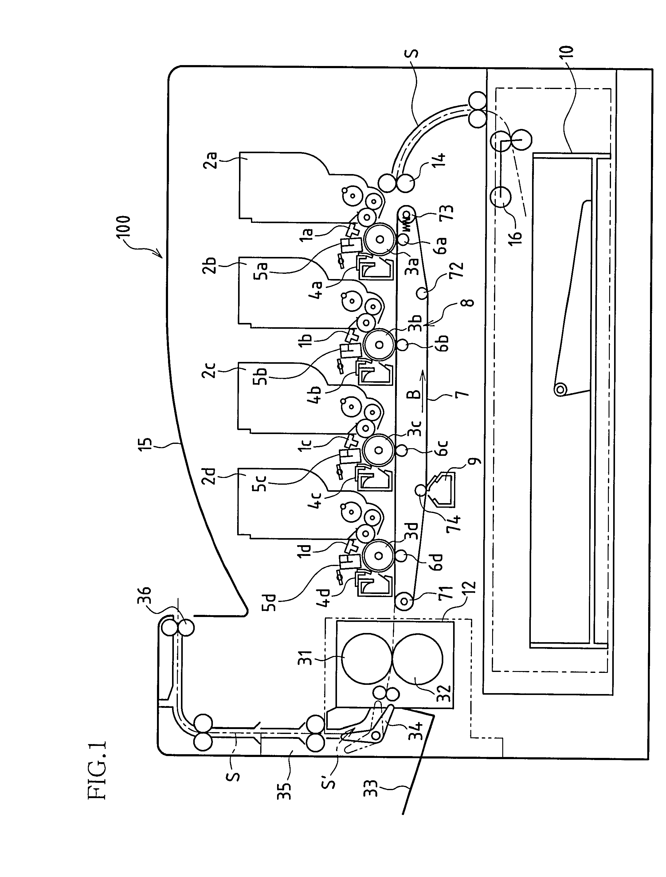
[0032]FIG. 1 is a schematic cross-sectional view showing a structure of a digital color multifunction machine (hereinafter, simply referred to as “multifunction machine”) 100 as a color image forming apparatus according to the present embodiment.

[0033] The multifunction machine 1001 is a system that forms multicolor and single color images on predetermined sheets (sheet of recording paper) in response to image data transmitted from an external portion and is constituted by items such as exposure units (1a, 1b, 1c, and 1d), development apparatuses 2, photosensitive drums 3, charging units (5a, 5b, 5c, and 5d), cleaning units (4a, 4b, 4c, and 4d), a transfer / transport belt unit 8, a fixing unit 12, a sheet transport path S, a paper feed tray 10, and discharge trays 15 and 33.

[0034...


PUM


Abstract

One embodiment of an image forming apparatus according to the present invention includes an image forming apparatus provided with a one-component development apparatus having a toner layer regulating blade for regulating a thickness of a toner layer on a surface of a developer bearing member that contacts a photosensitive body, wherein at a non-development time after completion of operation of the developer bearing member, the developer bearing member is caused to rotate slightly in a direction reverse to that during development.

Description

BACKGROUND OF THE INVENTION [0001] This application claims priority under 35 U.S.C. § 119(a) on Japanese Patent Application No. 2005-333034 filed in Japan on Nov. 17, 2005, the entire contents of which are hereby incorporated by reference. [0002] The present invention is applied to image forming apparatuses that carry out image formation electrophotographically such as copiers, printers, and facsimile machines, and particularly relates to image forming apparatuses that are effective in removing toner that has adhered to a toner layer regulating blade in an image forming apparatus in which a nonmagnetic one-component development apparatus is installed. [0003] Generally, in a nonmagnetic one-component development method, regardless of whether the toner is magnetic or nonmagnetic, a thin layer of charged one-component toner is formed on a developer bearing member and by conveying the thin layer by rotating a development roller to a development position facing a photosensitive drum on w...

Claims


Application Information

Patent Timeline
Patent Type & Authority Applications(United States)
IPC IPC(8): G03G15/08
CPCG03G15/0812G03G15/0818G03G2221/0005
Inventor KAZAKI, YUICHIKIDO, EIICHINAKAYA, HIROAKIYAMANAKA, TAKAYUKI
Owner SHARP KK
Why Eureka
Try Eureka