
Control logic for a propeller system

Active Publication Date: 2007-05-17
HAMILTON SUNDSTRAND CORP
View PDF17 Cites 27 Cited by
  • Summary
  • Abstract
  • Description
  • Claims
  • Application Information

AI Technical Summary

Benefits of technology

[0008] In addition to operating at all conditions, the present invention maintains closed-loop control of propeller speed for the maximum time possible whereas traditional methods control the propeller in an open-loop fashion. The closed-loop control method of operation permits the propeller speed governors to remain active for a greater percentage of time. This serves to minimize the magnitude of propeller overspeeds and / or propeller underspeeds that may otherwise occur during transitions into and out of reverse.

Problems solved by technology

However, conventional systems are typically optimized for only a subset of possible aircraft operating conditions and typically possess minimal control adjustment parameters for other speeds or altitudes of operation such that the propeller system may produce unacceptable levels of propeller speed overshoot or undershoot when not operating at the optimized aircraft operating condition.

Method used


Image

  • Control logic for a propeller system
  • Control logic for a propeller system
  • Control logic for a propeller system

Examples


Embodiment Construction

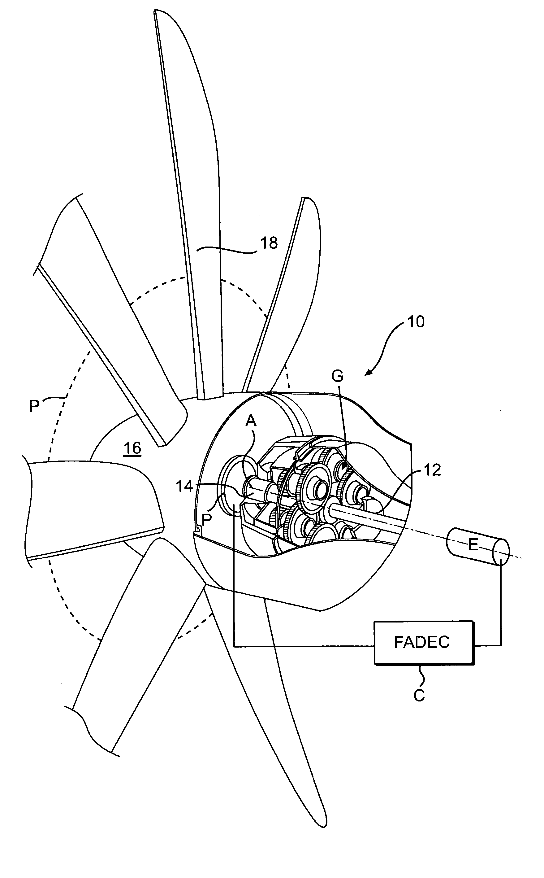
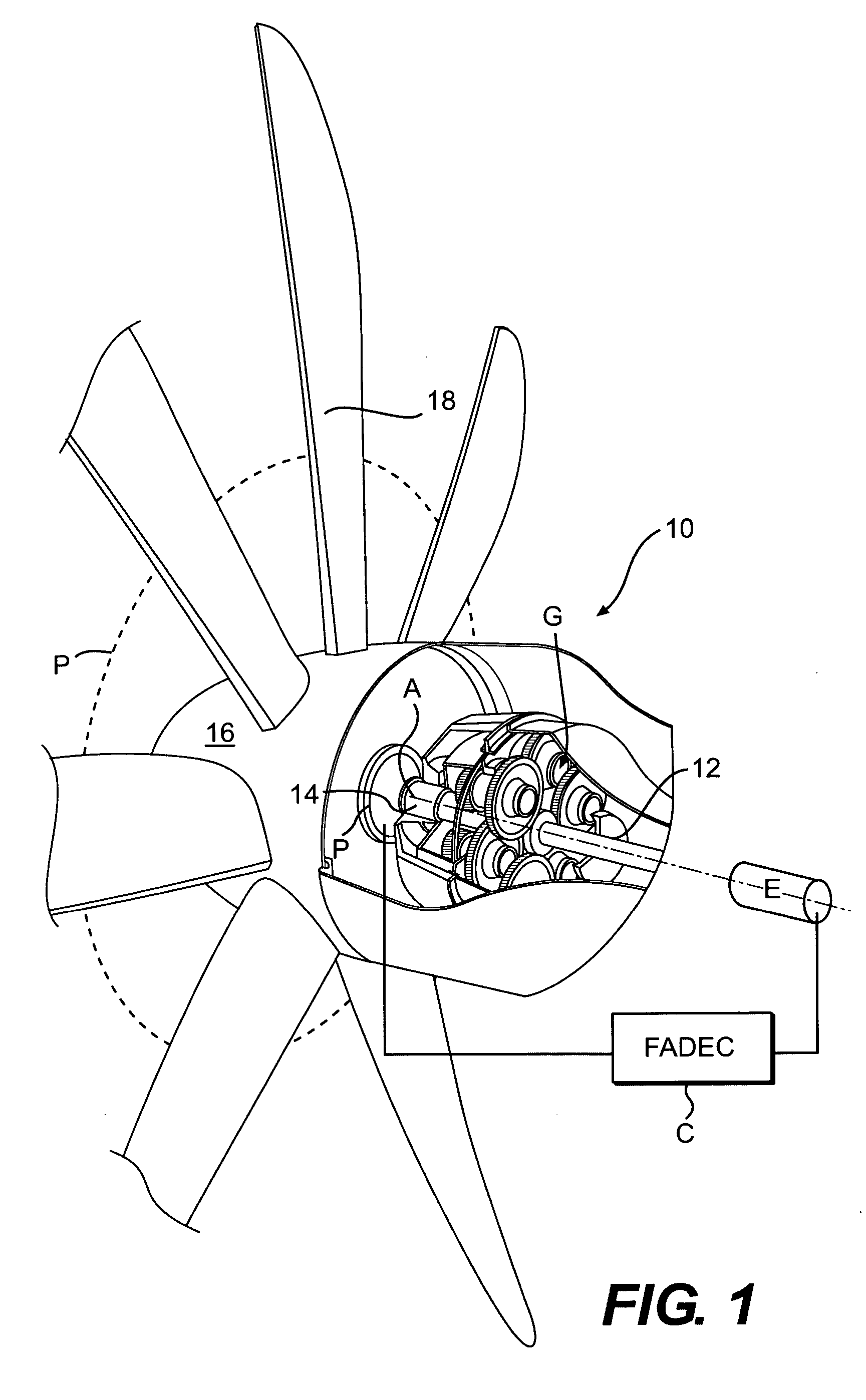
[0018]FIG. 1 illustrates a general perspective view of a propeller system 10 driven by a gas turbine engine (illustrated schematically at E). The engine E rotates a turbine output shaft 12 at a high speed to drive a gear reduction gearbox (illustrated somewhat schematically at G) which decreases shaft rotation speed and increases output torque. The engine E receives speed commands from a control C such as a Fully Automated Digital Electronic Control (FADEC). The gearbox G drives a propeller shaft 14 which rotates a hub assembly 16 and a plurality of propeller blades 18 which extend therefrom. The propeller blades 18 are mounted through a pitch control system P to have the ability to assume a negative blade angle which produces a reverse thrust. When the propeller system 10 is reversed, the propeller blades 18 are rotated below their positive angle, that is, through flat pitch, until a negative blade angle is obtained in order to produce a thrust acting in a direction opposite to for...


PUM


Abstract

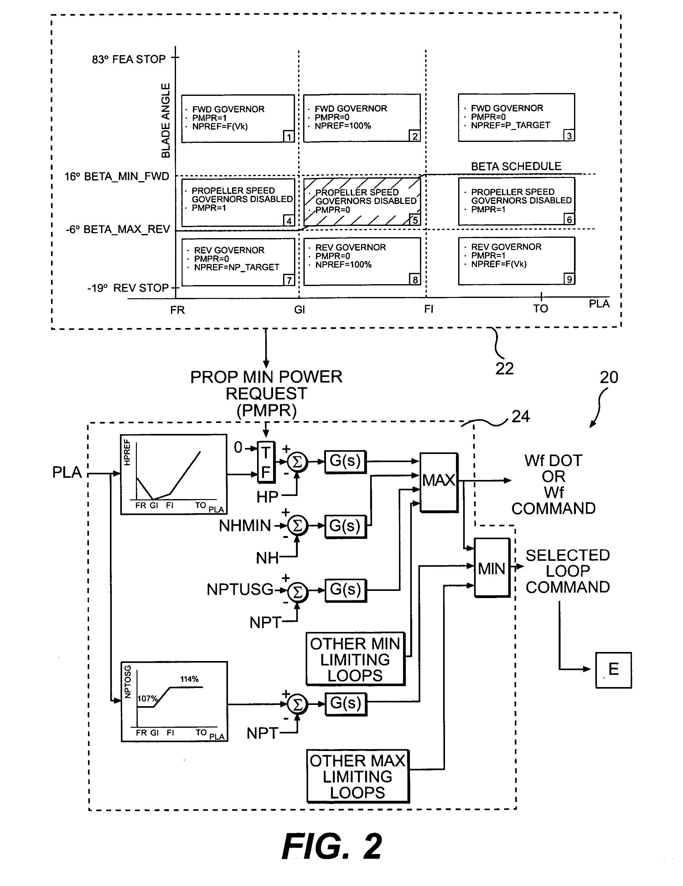
A propeller control system includes a propeller control logic subsystem in conjunction with an engine control logic subsystem to provide an optimized transition from forward to reverse speed governing under all operating conditions. By creating a Propeller control Mode (PCM) map relative the blade angle and Power Lever Angle (PLA), the minimum blade angle allowed for forward speed governing and the maximum blade angle allowed for reverse speed governing is determined. By combining the actual propeller blade angle, the min and max angles for speed governing, and the PLA signal, the state of the propeller speed governor is determined.

Description

BACKGROUND OF THE INVENTION [0001] The present invention relates to a propeller control system, and more particularly to pitch control logic which controls a transition from forward to reverse governing. [0002] Variable pitch propellers are employed on many differing types of aircraft having power plants ranging from piston engines to gas turbines. Conventional propeller control requires knowledge of when to deactivate the propeller speed governor and when the sense of the governor is to be inverted to provide for reverse thrust operation. [0003] The transition from forward to reverse governing requires passage through a zone known as the bucket of the Cp curve (propeller power coefficient versus propeller blade angle for a given advance ratio) where governing is not possible. On the right side of the Cp curve (where the curve has a positive slope), the speed governor must increase propeller blade angle as input power is increased to maintain a fixed speed. On the left side of the C...

Claims


Application Information

Patent Timeline
IPC IPC(8): B64C27/00
CPCB64C11/303B64C11/305B64C11/34
Inventor DANIELSON, DAVID R.
Owner HAMILTON SUNDSTRAND CORP
Learn More