Continuous polymer synthesizer

a polymer and synthesizer technology, applied in the direction of material analysis through optical means, instruments, specific gravity measurement, etc., can solve the problems of unwanted inefficiencies and substantial down time between synthesis reactions of instruments

Active Publication Date: 2007-05-17
ILLUMINA INC
View PDF44 Cites 36 Cited by
  • Summary
  • Abstract
  • Description
  • Claims
  • Application Information

AI Technical Summary

Benefits of technology

[0130] A requirement for a relatively large amount of energy can arise should the occasion of firing all valves simultaneously present itself to the HAL. In this case, enough current to source the spike of all of the valves can be stored locally. Any of a variety of capacitors known in the art can be used to store the current. Local storage of current reduces the instantaneous demand for current on the power supply used for the dispenser, thereby providing advantages of reducing the cost of the power supply and reducing the amount of space required to house the power supply. Thus, the HAL is typically configured to store at least an amount of energy sufficient to fire all of the valves simultaneously.

Problems solved by technology

Although a large number of such synthesizers can be employed to achieve relatively high throughput, this scale-up approach can result in unwanted inefficiencies.
An example of such inefficiency is the time that each synthesizer sits idle while waiting for individual incubation steps to be completed prior to delivery of the next reagent to any of the reactions.
Furthermore, instruments can experience substantial down time between synthesis reactions when new reaction vessels or reagents are reloaded.

Method used


Image

  • Continuous polymer synthesizer
  • Continuous polymer synthesizer
  • Continuous polymer synthesizer

Examples


Embodiment Construction

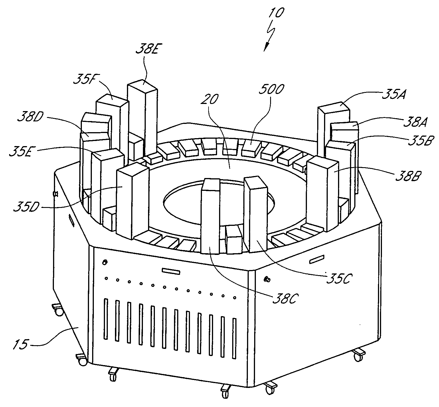
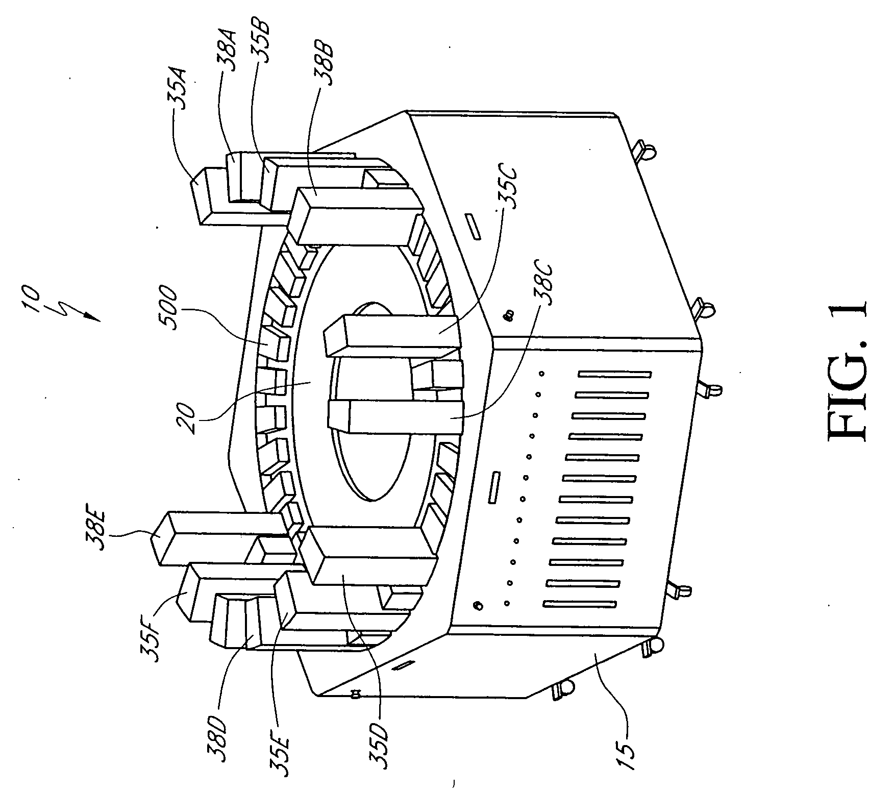
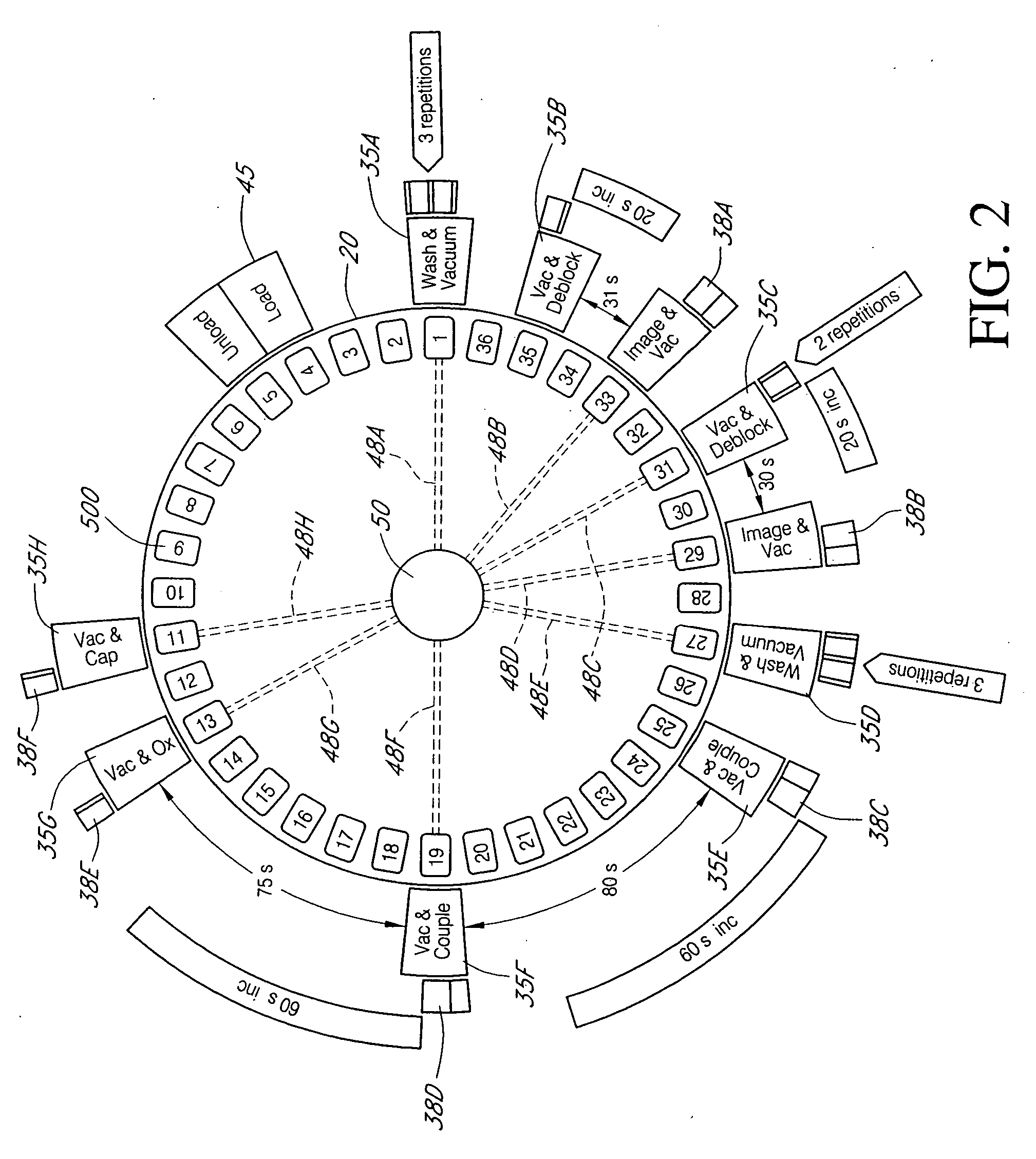
[0036] Some embodiments relate to a system for continuously synthesizing a plurality of different molecules, such as polymeric molecules. Systems of the embodiments can be configured to include an array of reaction sites and an array of stations for carrying out synthetic manipulations. The reaction sites in the array can be placed in a fixed order and at fixed intervals relative to each other. For example, an array of microtiter plates can be placed along the outer edge of a circular table. Each reaction site (i.e. well) can be assigned a different target product compared to the products to be synthesized at other reaction sites in the array. Similarly, the stations can be placed in a fixed order and at fixed intervals relative to each other. For example, the stations can be placed in a circular array having a perimeter that corresponds to the layout for the array of microtiter plates. Each of the stations can be configured to carry out a different manipulation compared to other st...


PUM

PropertyMeasurementUnit
period of timeaaaaaaaaaa
distancesaaaaaaaaaa
circumferenceaaaaaaaaaa

Abstract

Described is a system and method for synthesizing polymeric molecules such as oligonucleotides and polypeptides. The system is capable of continuously synthesizing molecules by providing an array of reaction sites and an array of stations for carrying out synthetic manipulations. The reaction sites in the former array can be placed in a fixed order and at fixed intervals relative to each other. Similarly, the stations can be placed in a fixed order and at fixed intervals relative to each other. The two arrays can be moved relative to each other such that the stations carry out desired steps of a reaction scheme at each reaction site. The relative locations of the stations and the schedule for the relative movement can correlate with the order and duration of reaction steps in the reaction scheme such that once a reaction site has completed a cycle of interacting with the full array of stations then the reaction scheme is complete.

Description

CROSS REFERENCE TO RELATED APPLICATIONS [0001] This application claims priority under 35 U.S.C. § 119(e) to U.S. Provisional Application No. 60 / 717,376 filed Sep. 14, 2005, which is hereby incorporated by reference in its entirety.BACKGROUND OF THE INVENTION [0002] 1. Field of the Invention [0003] The present embodiments relates to systems and methods for synthesizing molecules such as polymers. More specifically, the present embodiments relate to devices and methods for continuously synthesizing biological polymers such as polypeptides and oligonucleotides. [0004] 2. Description of the Related Art [0005] Oligonucleotides are among the most important and prevalent reagents used in biotechnology laboratories engaged in research, diagnostics and therapeutics. The high demand for oligonucleotides derives from their exquisite specificity for complementary nucleotide sequences in DNA or RNA obtained from biological samples. This specificity allows oligonucleotides to be used as probes th...

Claims


Application Information

Patent Timeline
Patent Type & Authority Applications(United States)
IPC IPC(8): B01J19/00
CPCB01J19/0046Y10T436/12B01J2219/00315B01J2219/00326B01J2219/0036B01J2219/00423B01J2219/00585B01J2219/0059B01J2219/00596B01J2219/00612B01J2219/00659B01J2219/00675B01J2219/00693B01J2219/00722B01J2219/00725B82Y30/00C40B60/14Y10T436/115831B01J2219/00283
Inventor HEINER, DAVID L.JONES, AARON C.FAMBRO, STEVEN P.NIBBE, MARK J.BURGETT, STEVE R.ELLMAN, BRETT M.LEBL, MICHAL
Owner ILLUMINA INC
Why Eureka
Try Eureka