
Container with a one-piece body

Inactive Publication Date: 2007-05-17
U S SMOKELESS TOBACCO COMPANY LLC
View PDF8 Cites 52 Cited by
  • Summary
  • Abstract
  • Description
  • Claims
  • Application Information

AI Technical Summary

Benefits of technology

[0011] Another aspect of the invention is a method of forming such containers. The method includes the steps of (1) drawing fibers into a first-cavity mold; (2) forming the fibers into an initial body shape within the first-cavity mold; (3) transferring the initial body shape to at least one further cavity mold; and (4) forming the initial body shape into the container body within the at least one furthe

Problems solved by technology

When molding a container, the draft of the container sidewalls often affects the performance of the mold and may limit the design that can be fabricated.
Such design limitation is often a shortcoming that restricts the design or shape that can be fabricated by molding.
The traditional, drafted container, such as one with a wider top than bottom, often creates difficulty with the application of a label to an outside side wall of the container.
A square or rectangular shaped label, for example, usually cannot be applied to the sidewall of a drafted container cleanly or easily.
Such combination (i.e., drafted container and rectangular label) may result in a label with wrinkles, creases, or bends that creates an unpleasing appearance.
To achieve a flat label, the drafted container usually requires a conic-shaped label that is often difficult to apply in a correct orientation; therefore, creating a skewed label that also presents an unpleasing appearance.
However, such improvements are usually only limited to specific materials.
For example, cellulose container one-piece bodies with non-drafted sides have previously been difficult to achieve because of the traditional limitations due to mold design.
Because the molding of non-drafted cellulose bodies for containers has previously been difficult, prior attempts to fabricate such non-drafted bodies for cellulose containers have focused on bonding multiple components.
Such multiple component structures lack strength and the bond may separate causing container body failure.
It is common, for example, that the bond between the structures may weaken or even separate upon contacting moisture.
Moreover, fabrication of such multiple-component bodies for containers is costly and complicated requiring multiple parts, adhesives, alignment issues, and additional process steps.

Method used


Image

  • Container with a one-piece body
  • Container with a one-piece body
  • Container with a one-piece body

Examples


example

[0063] This example provides a description of an exemplary fiber thermoforming operation used to form a fiber container body as described above. A molding machine was used to form the container body. The molding machine included a slurry tank, a vertically moveable platen for mounting a first cavity mold; a vertically and horizontally moveable platen for mounting a first transfer core; a stationary platen for mounting a second and third cavity mold; and a second vertically and horizontally moveable platen for mounting second and third transfer cores.

[0064] The slurry used to form the container body was prepared with about 99.3 percent ordinary tap water and about 0.7 percent cellulose pulp that was about 50 weight percent long, brown corrugate fiber and about 50 weight percent short, white paper fiber. The pulp fibers in the slurry tank were agitated and circulated for sufficient suspension. The slurry was maintained approximately at room temperature.

[0065] During pre-mold set-up,...


PUM

PropertyMeasurementUnit
Lengthaaaaaaaaaa
Lengthaaaaaaaaaa
Fractionaaaaaaaaaa

Abstract

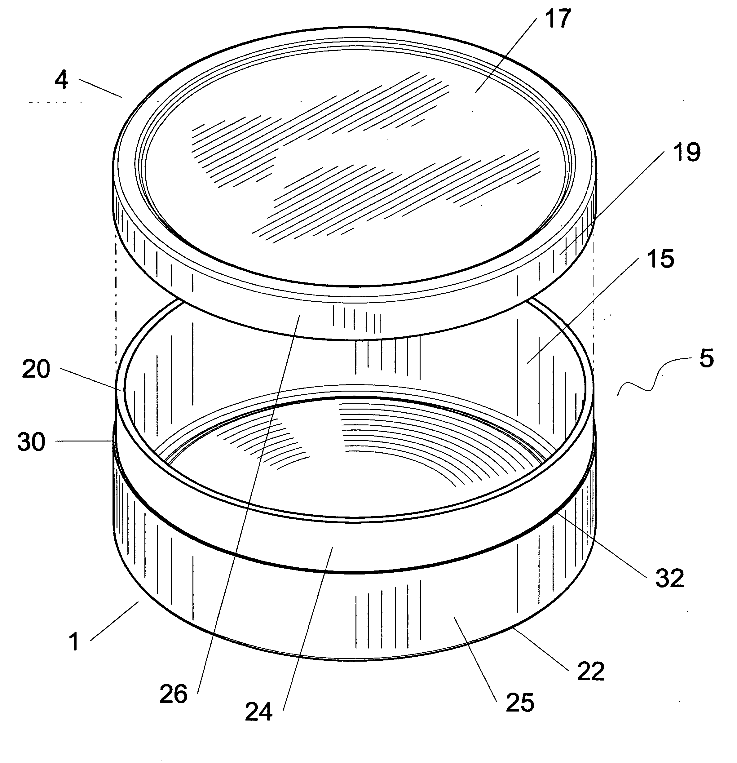
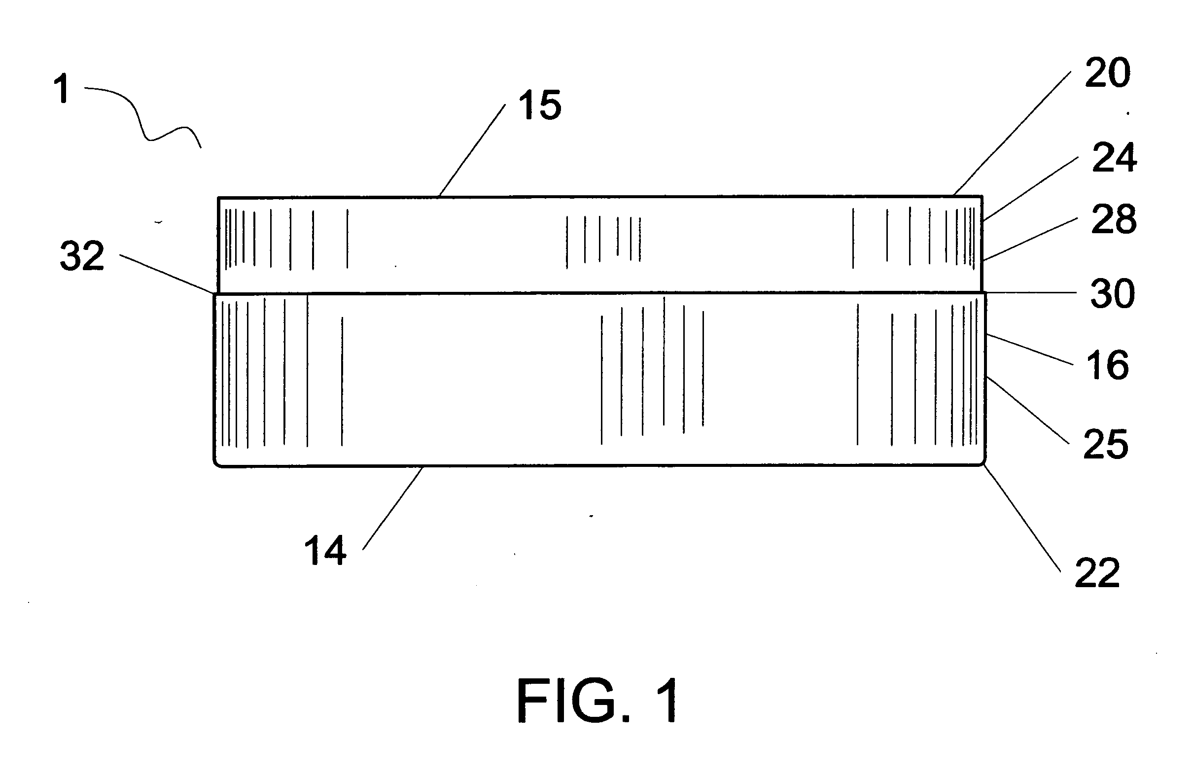
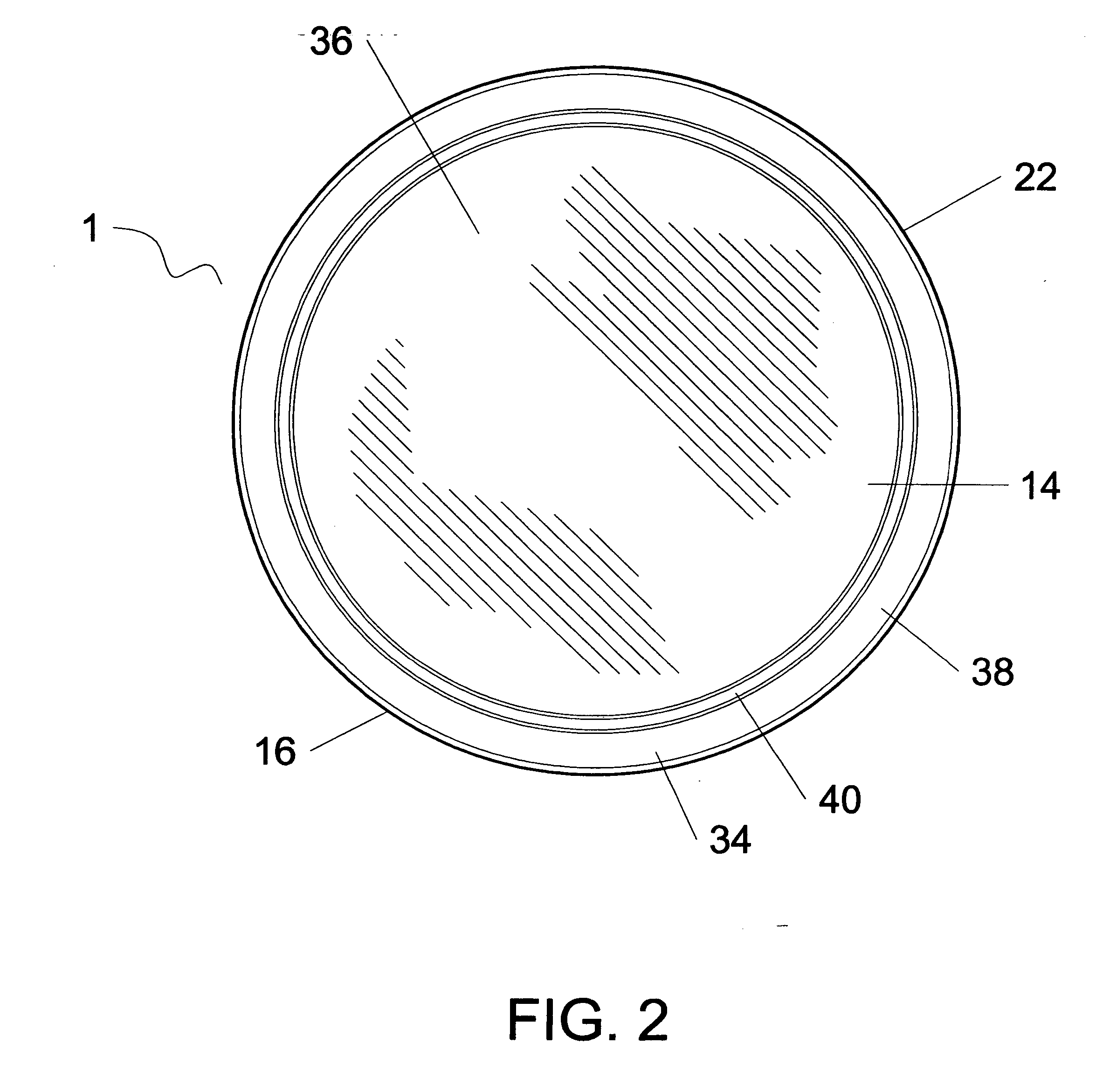
A container body, comprising a single fiber structure molded into the container body having an integral bottom portion and an integral side portion; an open cavity defined by the bottom portion and the side portion; and the side portion being perpendicular to the bottom portion such that a rectangular label is mountable to the side portion without creases.

Description

[0001] This application claims the benefit of U.S. Provisional Application No. 60 / 657,310, filed on Feb. 28, 2005.FIELD OF THE INVENTION [0002] The invention is directed to a container with a one-piece body, and a method of making thereof; more particularly, a one-piece, molded fiber body having non-drafted sidewalls and a method of making such body. BACKGROUND OF THE INVENTION [0003] Fabricating parts, such as bodies of containers, using a molding operation is a cost effective method to mass produce such parts. Injection molding, vacuum forming, and other molding operations are common examples of methods suitable to mass produce typical bodies for containers. When considering such methods, the design of the part as well as the material used are two factors that may affect the fabrication process. [0004] When molding a container, the draft of the container sidewalls often affects the performance of the mold and may limit the design that can be fabricated. Draft is the outward angle ...

Claims


Application Information

Patent Timeline
IPC IPC(8): B31B1/00B31B49/00B31B50/00
CPCB65D1/22B65D25/14B65D25/36Y10T428/13B65D2543/00092B65D2543/00277B65D2543/00537B65D43/0222
Inventor BRIED, DAVID K.PACE, GREGORY A.HOUK, GEORGE B.BARKER, MARTIN
Owner U S SMOKELESS TOBACCO COMPANY LLC
Learn More