
Device to measure acceleration and deceleration of hip rotation

a technology of acceleration and deceleration, which is applied in the field of hip rotation acceleration and deceleration devices, can solve the problems of not being able to teach a portable device that measures the acceleration or deceleration of the hip rotation, and prior methods have required expensive and time-consuming set-ups with body markers, computers and video cameras, etc., and achieves the effects of convenient use, low cost, and convenient us

Inactive Publication Date: 2007-05-17
PRICHARD ROBERT
View PDF6 Cites 17 Cited by
  • Summary
  • Abstract
  • Description
  • Claims
  • Application Information

AI Technical Summary

Benefits of technology

[0009] Another object of the invention is to provide a hip rotation measuring device that is worn by the user and gives immediate feedback regarding hip rotation acceleration and deceleration.
[0010] Another object of the invention is to provide a hip rotation measuring device that give immediate feedback to the wearer or instructor about the magnitude of the acceleration and deceleration of other body parts such as the hand, foot, shoulders and knee during a sport activity.
[0012] Yet another object of the invention is to provide a hip rotation measuring device that is inexpensive to manufacture.
[0013] Still yet another object of the invention is to provide a hip rotation measuring device that is light weight, portable and easily attached to the user so that it does not adversely affect the performance of the wearer during a sport activity.

Problems solved by technology

Until now, there has not been an easy, economical way for an athlete to measure his or her hip rotation acceleration or deceleration.
Prior methods have required expensive and time consuming set-ups with body markers, computers and video cameras.
However, none of the prior art specifically teaches a portable device that measures acceleration or deceleration of a body part.

Method used


Image

  • Device to measure acceleration and deceleration of hip rotation
  • Device to measure acceleration and deceleration of hip rotation
  • Device to measure acceleration and deceleration of hip rotation

Examples


Embodiment Construction

[0023] Detailed descriptions of the preferred embodiment are provided herein. It is to be understood, however, that the present invention may be embodied in various forms. Therefore, specific details disclosed herein are not to be interpreted as limiting, but rather as a basis for the claims and as a representative basis for teaching one skilled in the art to employ the present invention in virtually any appropriately detailed system, structure or manner.

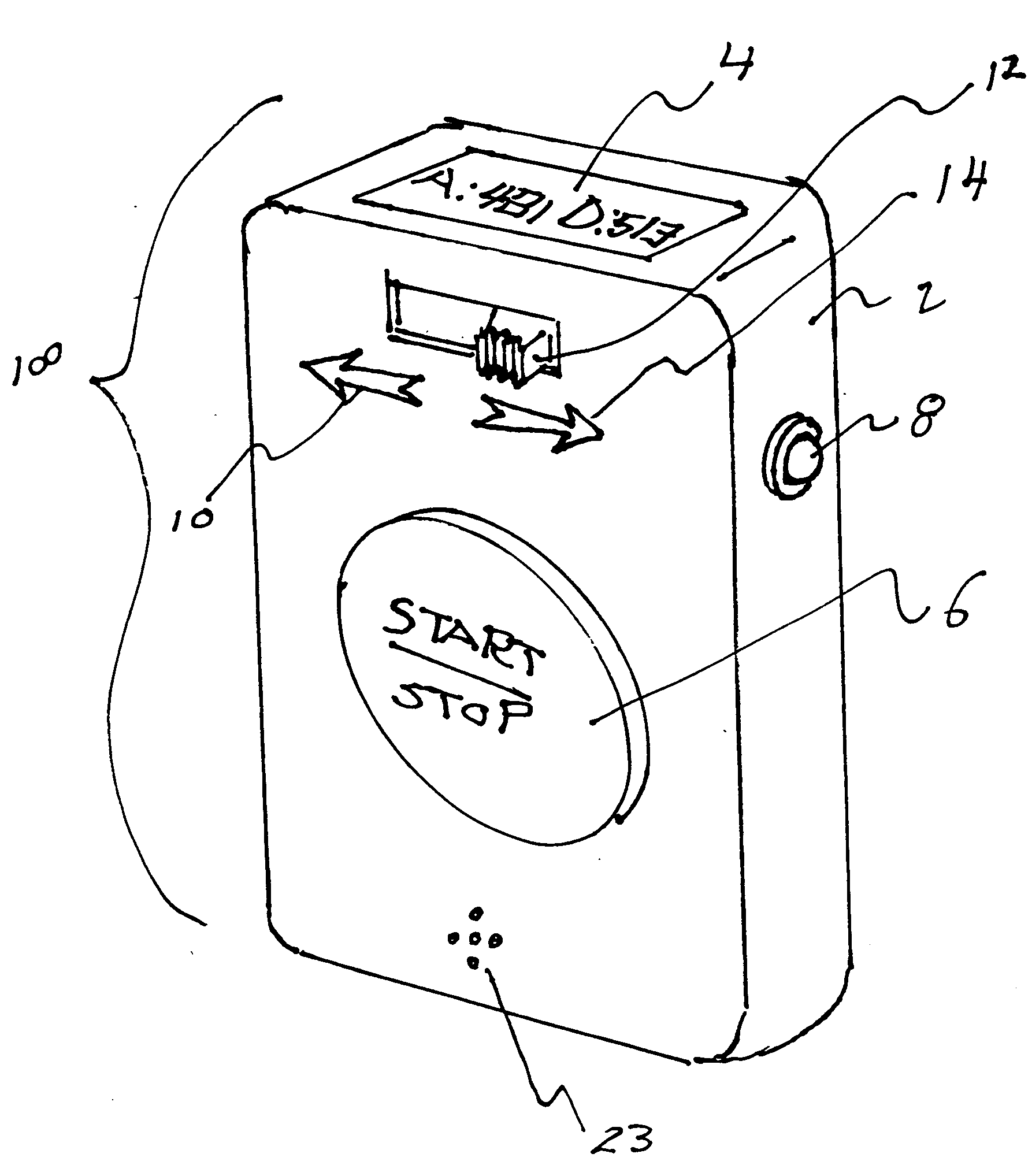
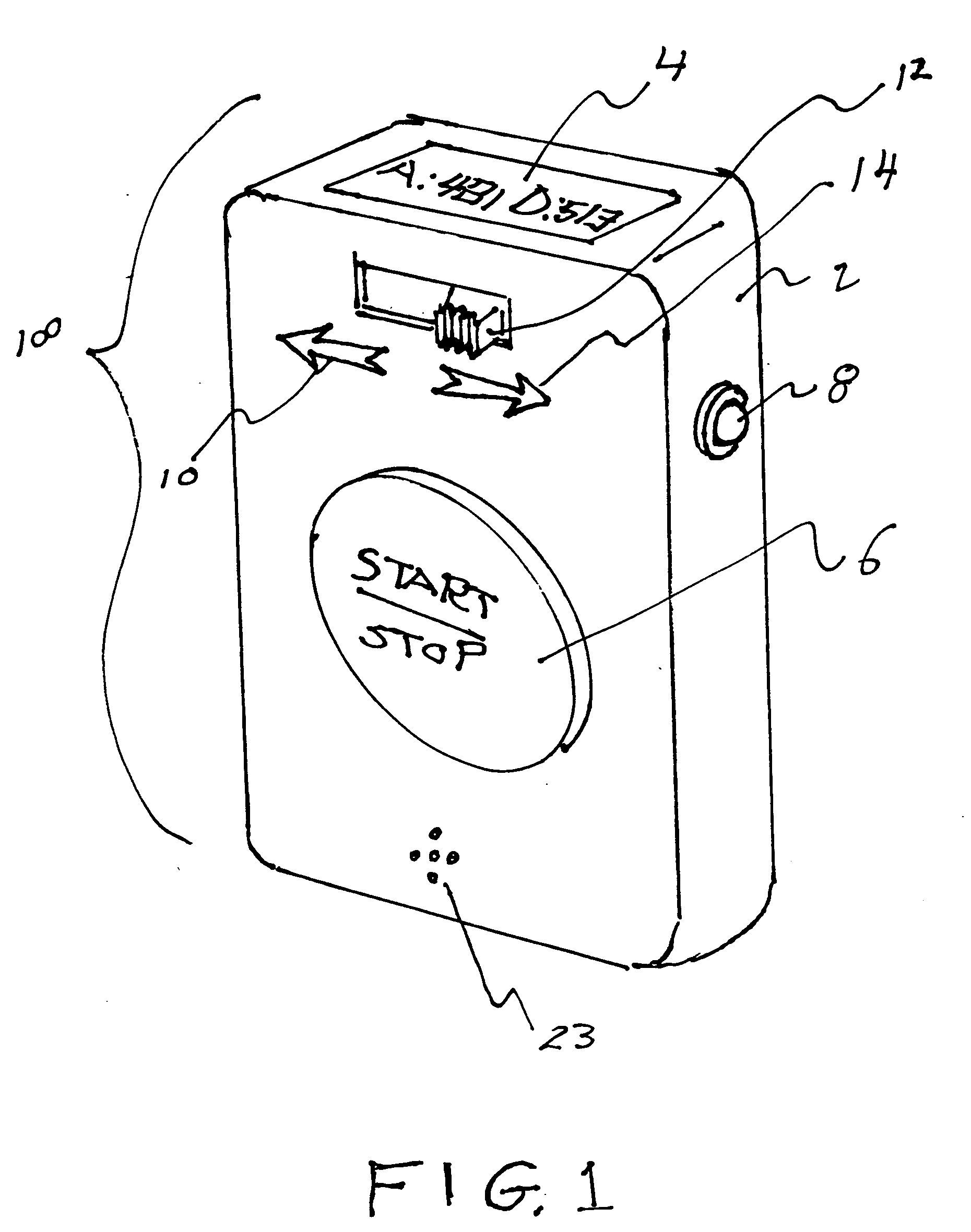
[0024] referring now to FIG. 1 we see a perspective view of the invention 100. The outer case 2 is smaller than a pack of cigarettes and therefore portable and capable of attaching to a person's clothing by a clip 26 or other standard fastening device as shown in FIG. 3. Push button 6 starts and stops the process of measuring acceleration or deceleration. Slide switch 12 lets the user select direction of acceleration measurement as shown by arrow 10 or by arrow 14. Push button 8 turns the entire unit on or off. Apertures 23 allow s...


PUM


Abstract

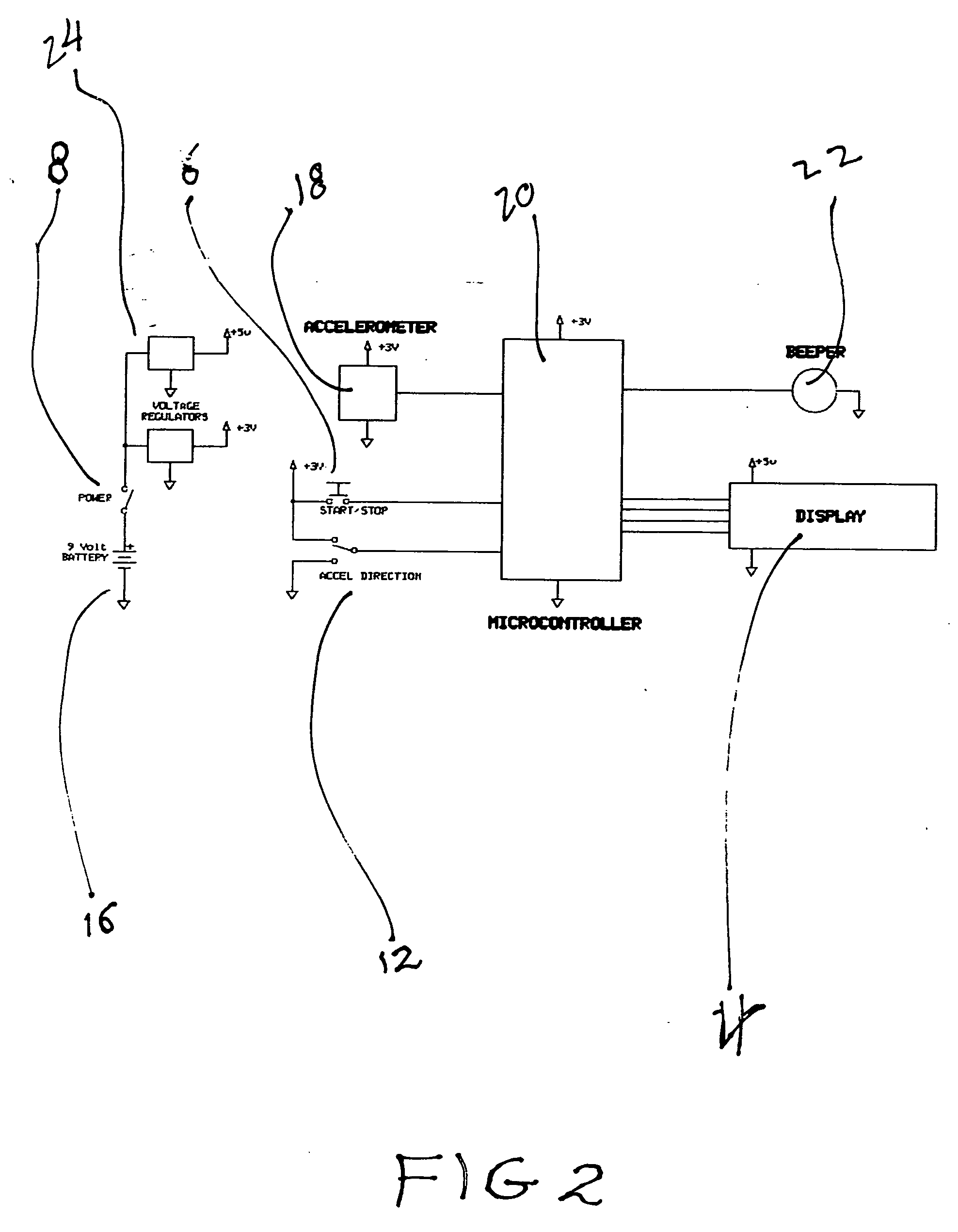
Hip rotation measuring device with an accelerometer, a micro-controller, a printed circuit board, a memory chip, a power supply such as batteries, an on-off switch, a start-stop recording switch, an acceleration direction switch an audible sound generator, a readout display such as an LCD display, standard support electronics such as resistors capacitors and regulators for operating the electronic components, a case to house the components, and a belt clip or other standard attachment device fixed to the outside of the case so that when the components are combined within the case and when the case is attached by the clip to an article of clothing that is in close proximity to a moving body part such as a hip, the readout display can show magnitude of acceleration or deceleration of hip movement of the user. The device can measure other body part acceleration and deceleration such as hand, foot, shoulders.

Description

CROSS REFERENCE TO RELATED APPLICATIONS [0001] Not Applicable STATEMENT REGARDING FEDERALLY SPONSORED RESEARCH OR DEVELOPMENT [0002] Not Applicable DESCRIPTION OF ATTACHED APPENDIX [0003] Not Applicable BACKGROUND OF THE INVENTION [0004] This invention relates generally to the field of electronic measuring devices and more specifically to a hip rotation measuring device. [0005] Research has shown that increasing hip rotation acceleration dramatically improves racquet head speed in tennis, bat speed in baseball, club speed in golf, hand speed in boxing, throwing speed in baseball and football, and even peak hand force in swimming. Better athletes are known to have higher rates of hip acceleration and deceleration during their sport than poorer performing athletes. Until now, there has not been an easy, economical way for an athlete to measure his or her hip rotation acceleration or deceleration. Prior methods have required expensive and time consuming set-ups with body markers, compu...

Claims


Application Information

Patent Timeline
Patent Type & Authority Applications(United States)
IPC IPC(8): A61B5/103
CPCA61B5/11A63B71/0619A61B5/4571A61B5/6831A61B2562/0219A63B69/00A63B69/0002A63B69/0015A63B69/002A63B69/004A63B69/3623A63B69/38A63B2071/0625A63B2220/40A63B2225/50A63B2244/15A63B2244/16A63B2244/20A63B69/3608A61B5/4528A61B5/7405
Inventor PRICHARD, ROBERT
Owner PRICHARD ROBERT
Learn More