Arrangement and method for detecting respiratory effort of a patient

a patient and breathing effort technology, applied in the field of arrangement and method of providing ventilation therapy to patients, can solve the problems of reducing the assistance provided to patients, affecting the detection effect of patients, and affecting the detection effect of actual patient breathing effort, so as to reduce the possibility of false readings, reduce the effect of confounding secondary effects, and eliminate the potential for false readings

Inactive Publication Date: 2007-05-24
GENERAL ELECTRIC CO
View PDF0 Cites 18 Cited by
  • Summary
  • Abstract
  • Description
  • Claims
  • Application Information

AI Technical Summary

Benefits of technology

[0007] In general, the present invention utilizes a sensor arranged to monitor flow and / or pressure changes within a breathing passage of the patient, which may include the nasal passages, mouth, throat, etc. Monitoring the changes in flow and / or pressure in the breathing passage of the patient according to the arrangements and methods described below provides accurate determination of actual patient attempts to breathe so that ventilatory support can be properly delivered to the patient at the appropriate time. The methods and arrangements of the present invention particularly distinguish between false patient triggers for the application of mechanical inspiratory breath supports. Such triggers including, but not limited to those caused by leaks in the patient breathing circuit and leaks between the patient / breathing circuit interface and the patient are distinguished from actual attempts by the patient to breathe. The methods and arrangements of the present invention also distinguish the detection of actual patient expiratory cycles over false detections that may be caused by compression of the breathing circuit. In one arrangement of the present invention, a patient / breathing circuit interface is adapted to provide a closed connection between a breathing passage of the patient and the breathing circuit. A sensing device is at least partially disposed in the breathing passage of the patient is arranged to sense a flow of gas through the breathing passage. A controller is provided that synchronizes respiratory support to the patient with actual patient attempts to breathe based upon the sensed flow of gas through the breathing passage of the patient.
[0008] The arrangement may further include a means for diverting or conditioning direct ventilator gas flow away from the sensing device or otherwise minimize confounding secondary effects of ventilator gas flows that do not contribute to gas flow into the patient breathing passages. The means may comprise a shield disposed between the facemask and the nasal passages of the patient. As gases flow into the facemask, the shield advantageously diverts and conditions the gas flow proximal to the sensor thus eliminating the potential for false readings by the sensor. Together, the sensor and shield promote improved detection of actual patient efforts to breathe. By this arrangement, attempts to breathe by the patient will result in a change in the flow of breathing gas in the patient's breathing passages, which is detected by the sensor and results in ventilatory support to the patient.

Problems solved by technology

In certain settings, such as intensive care, a patient that is connected to a ventilator is able to breath with shallow breathes but is unable to complete a proper breathing cycle on his or her own, or in doing so requires an excessive breathing effort.
This false identification would be due to the increased pressure in the facemask resulting from the inadvertent compression of the face mask.
Regardless, such a misinterpretation results in an asynchrony between the ventilator and the patient's respiratory efforts, ultimately reducing the assistance provided to the patient.
While these sensors are attached to the patient to monitor the occurrences of breathing, their responses tended to be slow, requiring greater than several tens or hundreds of milliseconds to measure the occurrence of a breath.
It is recognized that delays in triggering mechanical ventilation assistance can cause detrimental increase in the patient work of breathing or in extreme breath dysynchrony may cause the ventilator to oppose the patient's breathing effort.
The long time delay between detection of the patient's spontaneous breathing attempt and the application of mechanical ventilation assistance makes these apnea or breath detection sensors unsuitable to synchronize mechanical ventilation support of non-intubated patient.

Method used


Image

  • Arrangement and method for detecting respiratory effort of a patient
  • Arrangement and method for detecting respiratory effort of a patient
  • Arrangement and method for detecting respiratory effort of a patient

Examples


Embodiment Construction

[0019] In the preferred embodiments of the present invention described in detail below, an arrangement and method for detecting spontaneous respiratory efforts of a patient is provided. It should be understood that the drawings and specification are to be considered an exemplification of the principles of the invention, which is more particularly defined in the appended claims.

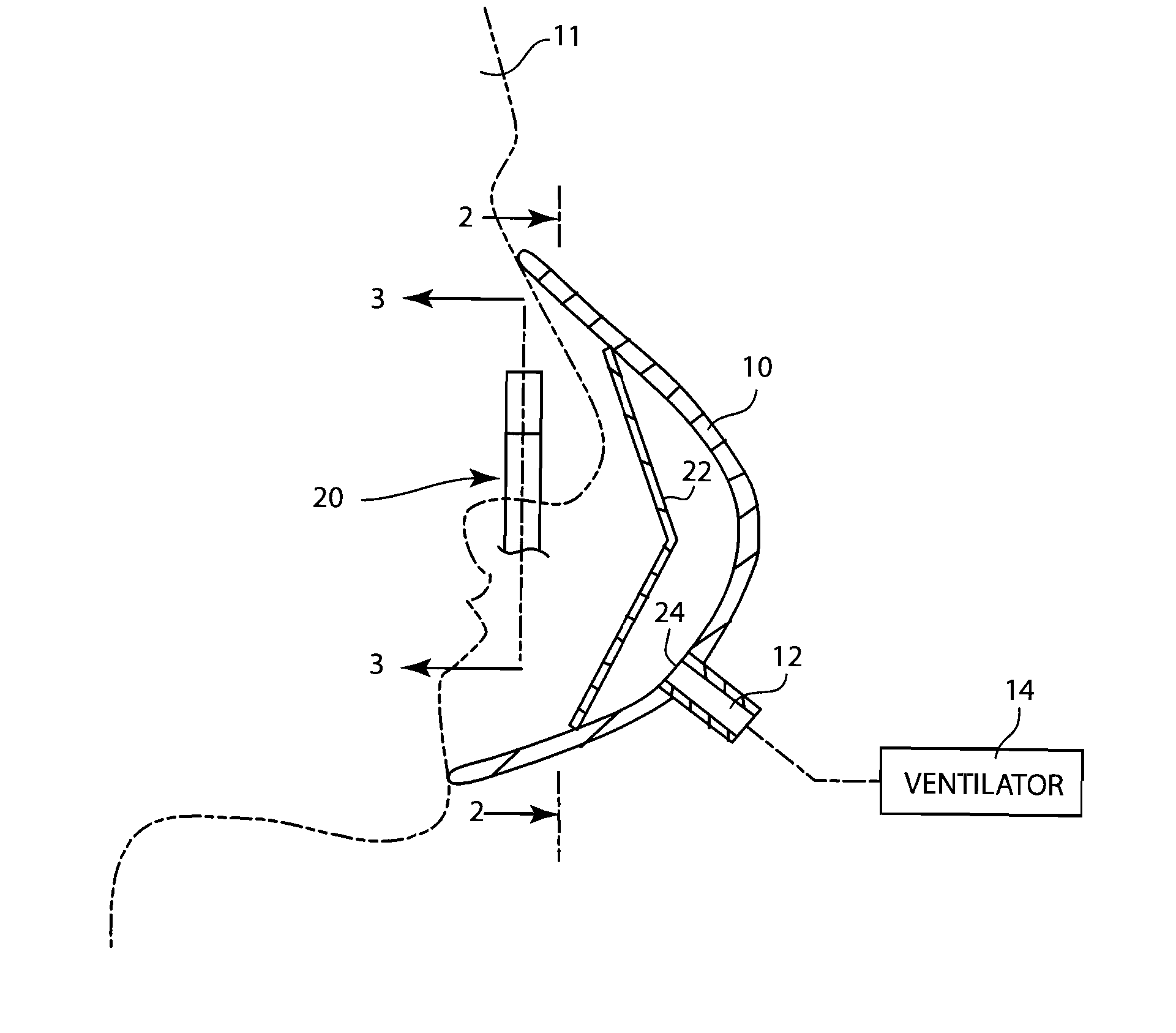
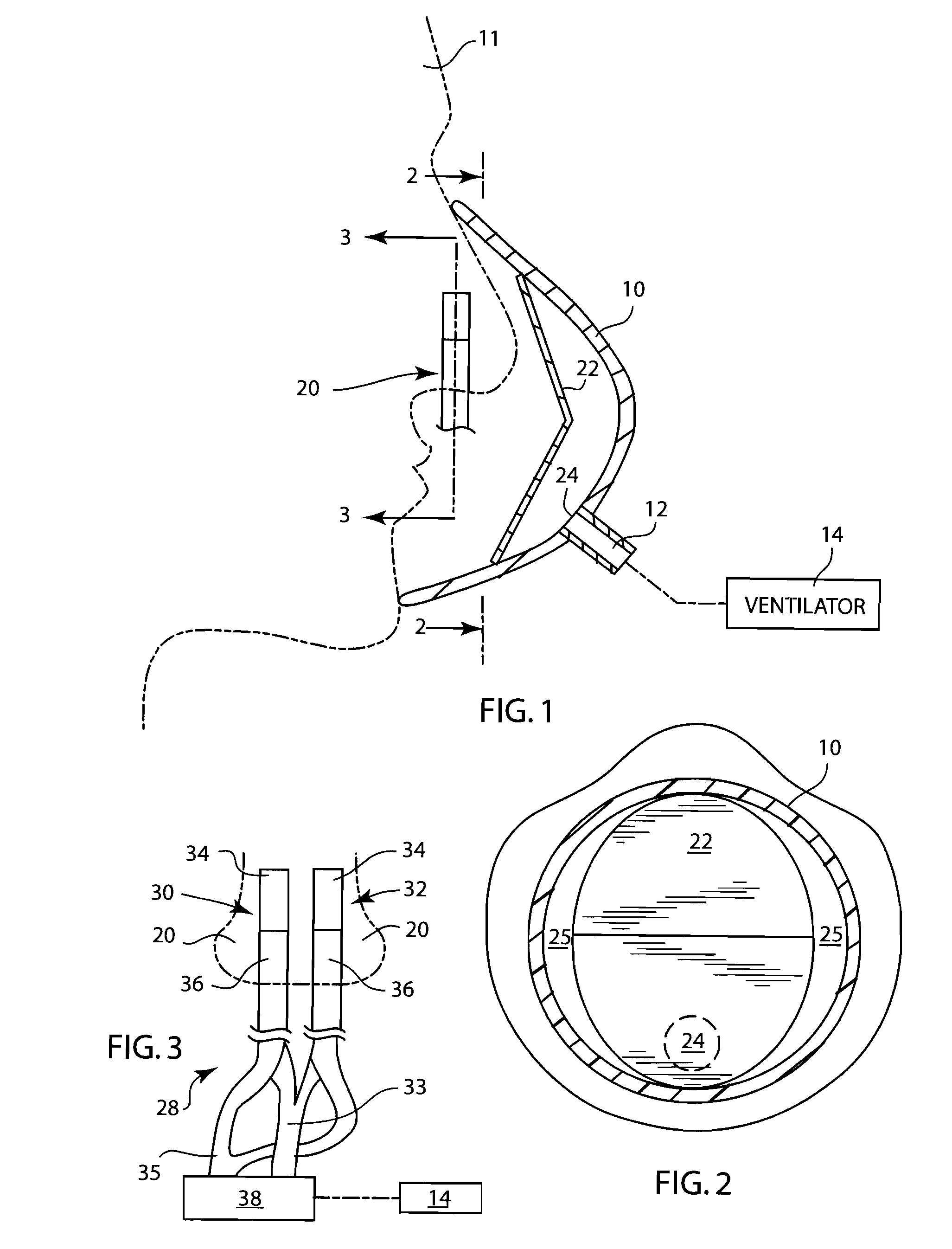
[0020] Referring to FIG. 1, an arrangement for detecting actual spontaneous respiratory effort of a patient 11 receiving ventilatory support via a patient breathing circuit 12 is shown. The breathing circuit 12 is connected to the patient 11 via a patient / breathing circuit interface, which in the embodiment shown is a facemask 10, which is suitable for positive airway pressure ventilation. The facemask 10 is adapted to provide a closed connection between a breathing passage of the patient, which in FIG. 1 comprises the patient's nasal passages 20, and the breathing circuit 12. The facemask 10 and breathing ci...


PUM


Abstract

An arrangement and method for detecting spontaneous respiratory effort of a patient receiving ventilatory support via a breathing circuit. A patient / breathing circuit interface is adapted to provide a closed connection between a breathing passage of the patient and the breathing circuit. A sensor is disposed at least partially in the breathing passage of the patient and arranged to sense flow of gas through the breathing passage. The arrangement and method individually or in addition to the airway pressure measurement promotes reliable and rapid detection of breathing efforts of a non-intubated patient to promote efficient augmentation of patient breathing.

Description

FIELD OF THE INVENTION [0001] The present invention relates to an arrangement and method for providing ventilation therapy to a patient. In general, the present invention relates to an arrangement and method for detecting patient breathing efforts such that suitable ventilatory pressure support is timely provided to the patient. BACKGROUND AND SUMMARY [0002] Patients that have ventilatory difficulties are often placed on a ventilator. A ventilator is a mechanical device designed to provide all or part of the work a body must produce to move gas into and out of the lungs. The ventilator delivers breathable gas to a patient and carries expired gas from the patient through a set of flexible tubes called a “patient breathing circuit”. [0003] In many instances, the patient is connected to the patient breathing circuit via a “patient / breathing circuit interface”. The patient / breathing circuit interface may comprise of any one of a variety of devices that create a seal with the patient's f...

Claims


Application Information

Patent Timeline
Patent Type & Authority Applications(United States)
IPC IPC(8): A61M16/00A61B5/08
CPCA61M16/00A61M16/06A61M2016/0036A61M2230/40A61M16/021A61M16/0627A61M16/0672A61B5/08A61B5/0816A61B5/0826A61B5/087A61B5/091
Inventor DELISLE, MATT S.THAM, ROBERT Q.BATHE, DUNCAN P.L.
Owner GENERAL ELECTRIC CO
Why Eureka
Try Eureka