Time of flight mass spectrometer

a mass spectrometer and time-of-flight technology, applied in mass spectrometers, separation processes, dispersed particle separation, etc., can solve the problems of limited overall size, limited flight distance, and inability to produce an adequate strength of electric field in construction, so as to improve the mass resolution, improve the effect of mass resolution and strengthen the magnetic field

Inactive Publication Date: 2007-05-24
SHIMADZU CORP
View PDF1 Cites 9 Cited by
  • Summary
  • Abstract
  • Description
  • Claims
  • Application Information

AI Technical Summary

Benefits of technology

[0018] According to this construction, ions that have their paths deflected in the axial direction by the first deflecting magnetic field have their paths deflected to the opposite direction by the second deflecting magnetic field. If both deflecting magnetic fields are tuned to produce the same amount of deflection in the axial direction, the flight paths of the ions that have passed through the second deflecting magnetic field are on a plane perpendicular to the axial direction. The real amount of deflection in the axial direction depends on the distance between the exit of the first deflecting magnetic field and the entrance of the second deflecting magnetic field. This construction makes the ions fly on a plane perpendicular to the axial direction within every electric sector field so that the ions are prevented from spreading in the axial direction.
[0019] The magnetic field generator may use either permanent magnets or electromagnets. Use of electromagnets enables an arbitrary control of the amount of deflection of the ions per turn by changing the strength of the magnetic f

Problems solved by technology

However, conventional types of TOFMSs (e.g. a linear type, reflectron type and so on) have physical restrictions (e.g. the limited overall size) that limit their flight distance.
However, the above-described construction has a problem in that an ion having a smaller mass-to-charge ratio and flying at an accordingly higher speed may overtake another

Method used


Image

  • Time of flight mass spectrometer
  • Time of flight mass spectrometer
  • Time of flight mass spectrometer

Examples


first embodiment

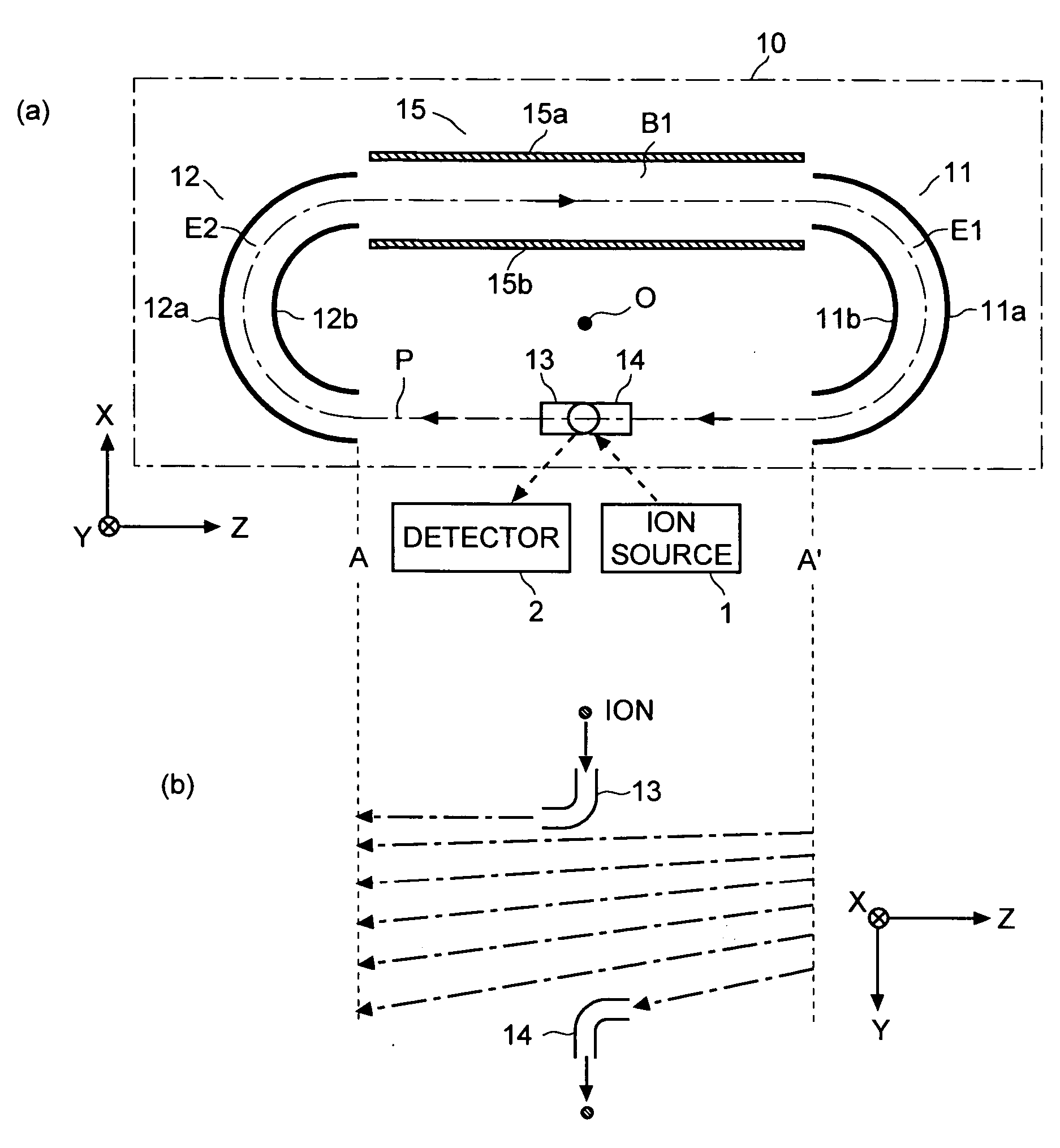
[0041] the time of flight mass spectrometer (TOFMS) according to the present invention is described with reference to the drawings. FIG. 1 schematically shows the construction of the main components of the TOFMS of the present embodiment, including the flight space. In FIG. 1, (a) is a plan view of the flight space 10 and (b) is a side view of the flight path of the ions within the space between A-A′ in (a). For this construction, a three-dimensional orthogonal coordinates system having three axes of X, Y and Z is defined as shown in FIGS. 1(a) and 1(b).

[0042] The TOFMS of the present embodiment includes an ion optics system having a pair of cylindrical electrodes 11 and 12 spaced apart by a predetermined distance along the Z-axis within the flight space 10. The cylindrical electrode 11 (or 12) consists of sector-shaped outer and inner electrodes 11a and 11b (or 12a and 12b). These electrodes 11a, 11b, 12a and 12b can be created by setting a double-wall cylinder parallel to the Y-ax...

second embodiment

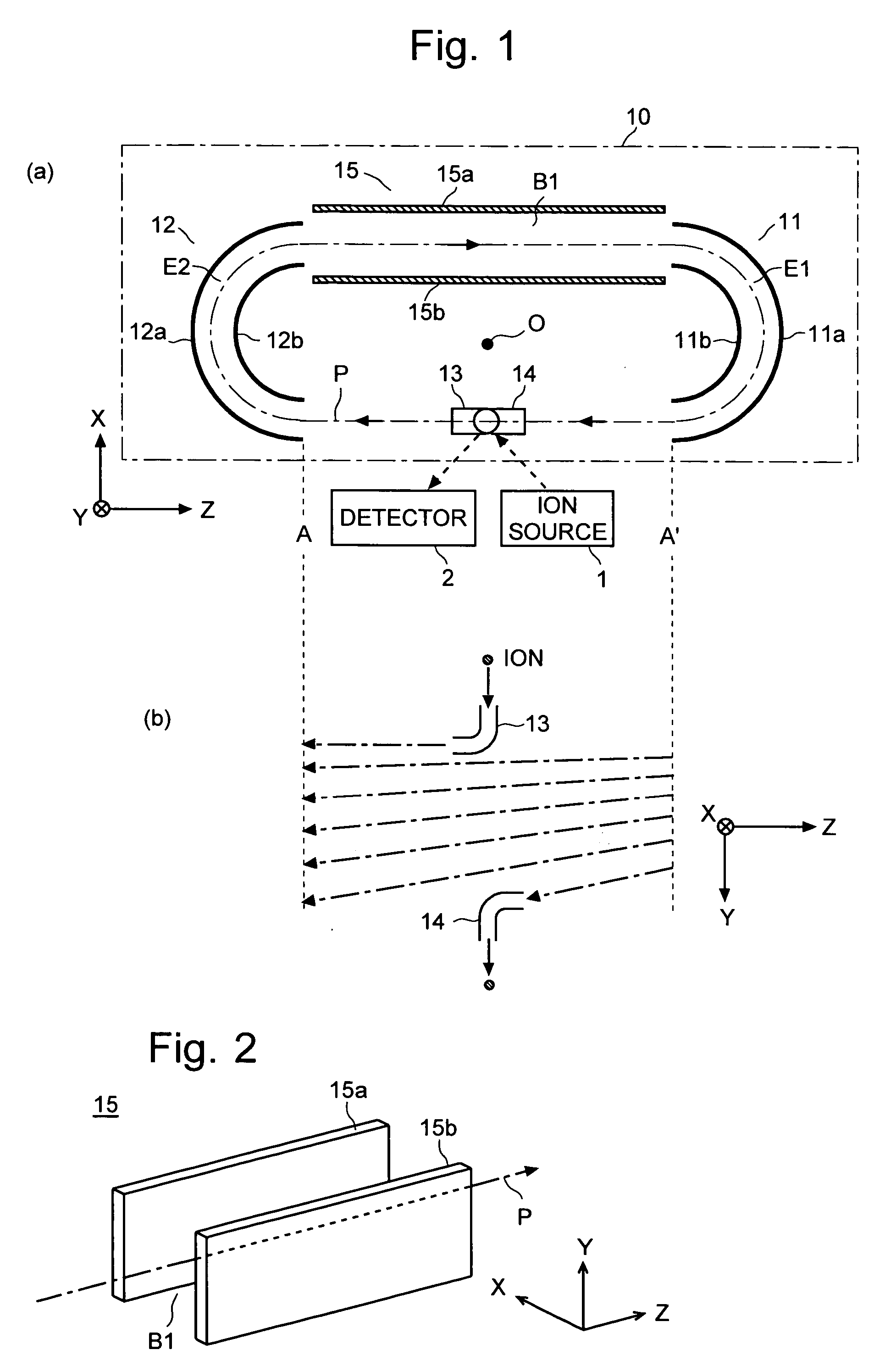
[0050]FIG. 5 schematically shows the construction of the main components of the TOFMS of another embodiment (the second embodiment), including the flight space. In the present embodiment, the TOFMS has two magnetic field generators: the first magnetic field generator 15 for creating the deflecting magnetic field B1 in the linear section of the flight path between the exit of the cylindrical electrode 12 and the entrance of the cylindrical electrode 11; and the second magnetic field generator 16 for creating another deflecting magnetic field B2 in the linear section of the flight path between the exit of the cylindrical electrode 11 and the entrance of the cylindrical electrode 12. The second magnetic field generator 16 has a parallel pair of planer magnetic poles 16a and 16b spaced apart in the X-direction and facing each other across the central path P of the ions.

[0051] The direction of the magnetic field of the deflecting magnetic field B2 created by the second magnetic field gen...


PUM


Abstract

In a time of flight mass spectrometer (TOFMS) having a flight space in which ions fly in a loop orbit formed by a plurality of electric sector fields, the present invention provides a simple structure that creates a spiral path by deflecting the ions in the axial direction of the electric fields at every turn of the ions. In a mode of the present invention, the TOFMS has cylindrical electrodes 11 and 12 for creating electric sector fields E1 and E2, between which a parallel pair of planer magnetic poles 15a and 15b are provided. The planer magnetic poles 15a and 15b create a deflecting magnetic field B1 for shifting the ions in the axial direction (Y-direction) of the electric sector fields. The ions experience a Lorenz force once every turn when they pass through the deflecting magnetic field B1. This construction uses only one pair of magnetic poles facing each other across the ion path P to deflect every ion irrespective of its number of turns. There is no need to provide one deflector for each turn of the ions, as in the case of conventional TOFMSs.

Description

[0001] The present invention relates to a time of flight mass spectrometer. More specifically, it relates to a time of flight mass spectrometer comprising plural electric sectors for making ions fly along a loop orbit. BACKGROUND OF THE INVENTION [0002] In general, a time of flight mass spectrometer (TOFMS) accelerates ions by an electric field to a certain level of kinetic energy and injects them into a flight space having a specific flight distance. In the flight space, the ions are separated by their mass-to-charge ratios according to the time of flight (or “flight time”) until they are detected by a detector. The difference in the flight time of two ions having different mass-to-charge ratios is larger as the flight distance is longer. Therefore, it is possible to enhance the mass resolution by making the flight distance longer. However, conventional types of TOFMSs (e.g. a linear type, reflectron type and so on) have physical restrictions (e.g. the limited overall size) that li...

Claims


Application Information

Patent Timeline
IPC IPC(8): H01J49/00
CPCH01J49/30H01J49/408
Inventor UENO, YOSHIHIRO
Owner SHIMADZU CORP
Why Eureka
Try Eureka