Three-Dimensional Luminescent Display and Method for Using the Same
a luminescent display and three-dimensional technology, applied in the field of luminescent displays, can solve the problems of quite inconvenient wearing glasses for viewers, and achieve the effects of high luminance, high resolution, and quick response tim
- Summary
- Abstract
- Description
- Claims
- Application Information
AI Technical Summary
Benefits of technology
Problems solved by technology
Method used
Image
Examples
first embodiment
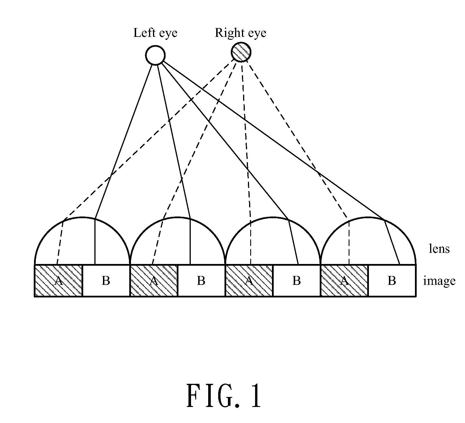
[0024] the present invention discloses a 3D luminescent display as shown in FIG. 2. A first substrate 101 made from glass has a first surface 101A and a second surface 101B. A second substrate 102 made from glass has a first surface 102A and a second surface 102B.
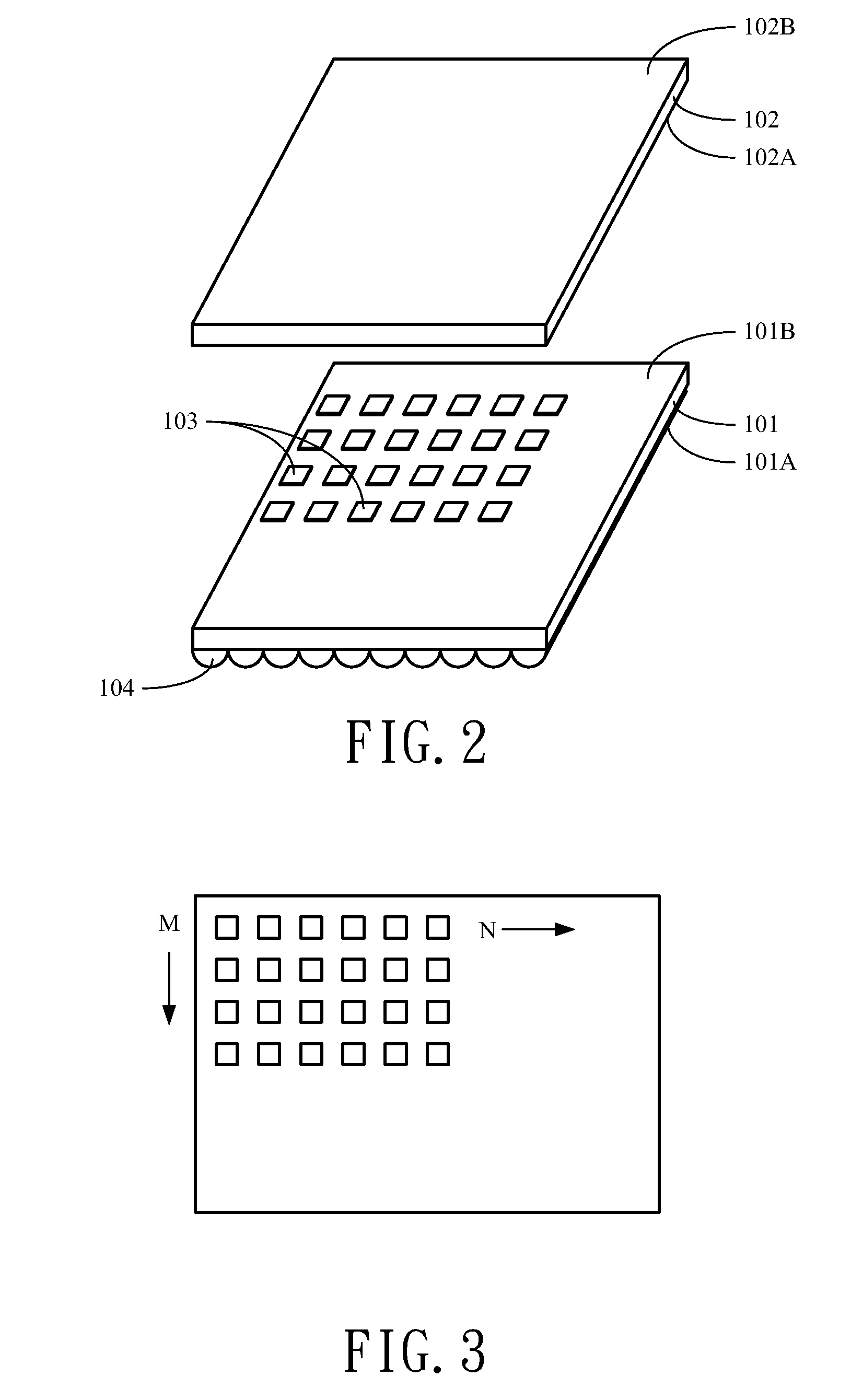
[0025] A plurality of light emitting devices 103 are provided on the second surface 101B of the first substrate 101. Each light emitting device comprises a pixel and every pixel has a square shape. The distance between the two neighboring pixels (pitch) is 0.00278 inch (0.0706 mm). As shown in FIG. 3, the pixels form a matrix with N×M pixels where N=768 (256*3) and M=768.
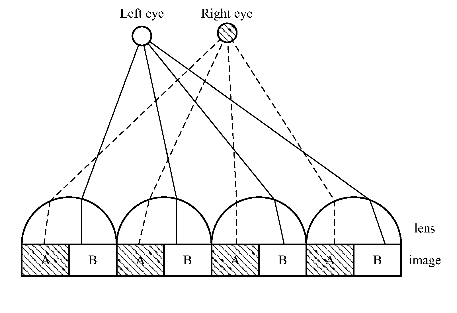
[0026] A plurality of linear lenticular lenses are provided on the first surface 101A of the first substrate 101. As shown in FIGS. 4A and 4B, these lenticular lenses 104 form a linear array. There are 30 linear lenticular lenses per inch, i.e. 30LPI. The lenticular lenses can be obtained from a commercial lenticular sheet. Other than cylindrical lenses, t...
second embodiment
[0028] the present invention discloses a 3D luminescent display as shown in FIG. 5. A first substrate 101 made from glass has a first surface 101A and a second surface 101B. A second substrate 102 made from glass has a first surface 102A and a second surface 102B.
[0029] A plurality of light emitting devices 103 are provided on the second surface 101B of the first substrate 101. Each light emitting device comprises a pixel and every pixel has a square shape. The distance between the two neighboring pixels (pitch) is 0.00278 inch (0.0706 mm). Like those in the first embodiment shown in FIG. 3, the pixels also form a matrix with N×M pixels where N=768 (256*3) and M=768.
[0030] A plurality of linear lenticular lenses are provided on the second surface 102B of the second substrate 102. Like those in the first embodiment shown in FIGS. 4A and 4B, the lenticular lenses 104 form a linear array. There are 30 linear lenticular lenses per inch, i.e. 30LPI. The lenticular lenses can be obtained...
fourth embodiment
[0033] the present invention discloses a method for using the 3D luminescent display. At first, the 3D luminescent display according to the present invention is provided. Twelve (3*4) images for multiple viewpoints on the three-dimensional luminescent display are simultaneously displayed to show 3D effect. The 12 images are interlaced along the M direction of the N by M matrix to form a composite image on the display and the 12 pixels (4 sets of R, G, B pixels) along the N direction are treated as one displaying pixel to show the same image data.
[0034] To sum up, the present invention discloses a luminescent display comprising lenticular lenses to display 3D images. Furthermore, the present invention discloses a method for using the 3D luminescent display. Because the luminescent displays have the advantages of high luminance, quick response time, high resolution, compared to the LCD, the 3D display according to the present invention can display 3D pictures with high quality and hig...
PUM
 Abstract
Description
Claims
Application Information
 - R&D
- Intellectual Property
- Life Sciences
- Materials
- Tech Scout
- Unparalleled Data Quality
- Higher Quality Content
- 60% Fewer Hallucinations
Browse by: Latest US Patents, China's latest patents, Technical Efficacy Thesaurus, Application Domain, Technology Topic, Popular Technical Reports.
© 2025 PatSnap. All rights reserved.Legal|Privacy policy|Modern Slavery Act Transparency Statement|Sitemap|About US| Contact US: help@patsnap.com


