Dual camera calibration technique for video projection systems

a video projection and calibration technology, applied in the field of video projection, can solve the problems of low resolution, low cost, and general use of expensive optics, and achieve the effect of low resolution and low cos

Inactive Publication Date: 2007-05-24
FAKESPACE LABS
View PDF1 Cites 22 Cited by
  • Summary
  • Abstract
  • Description
  • Claims
  • Application Information

AI Technical Summary

Benefits of technology

[0011] A video projection calibration technique includes a first camera to view the video display screen from the projector side, and a second camera to view the video display screen from the viewing side. The first camera may be a lower resolution than the second camera. The combination of the two cameras permits the transfer functions of the projection system and the first camera to be characterized and reduced to a warping transform that may be stored by the control system. The presence of the warping transform would permit the lower resolution, first camera to perform image realignment after the video projection system is in use by an end user.

Problems solved by technology

In order to provide a crisp, distortion free image on a thin-cabinet (small depth) large screen rear projection monitor without the aid of an image warping system, very expensive optics are generally employed.
Lower cost large screen rear projection monitors that have lower-cost optics either cannot be thin-cabinet, to avoid distorting the image projected on to the monitor screen, or the image quality on the monitor screen is inferior to that of a more expensive system using better optics.
Image warping systems negate the need for expensive optics by pre-warping an image from a video input device (such as a television tuner, DVD player, or the like) before the image is projected onto the monitor screen.
Loose manufacturing tolerances and other factors may cause each large screen rear projection monitor to require different warping transformations.
Shipping and handling a large screen rear projection monitor may cause optical components to shift or move out of alignment, and environmental effects (humidity, temperature changes, and the like) can also cause these problems.
These alignment problems may cause projected images to shift on-screen (either up-down, left-right, or rotationally).
Obviously, these effects are still objectionable to the consumer.

Method used


Image

  • Dual camera calibration technique for video projection systems
  • Dual camera calibration technique for video projection systems
  • Dual camera calibration technique for video projection systems

Examples


Embodiment Construction

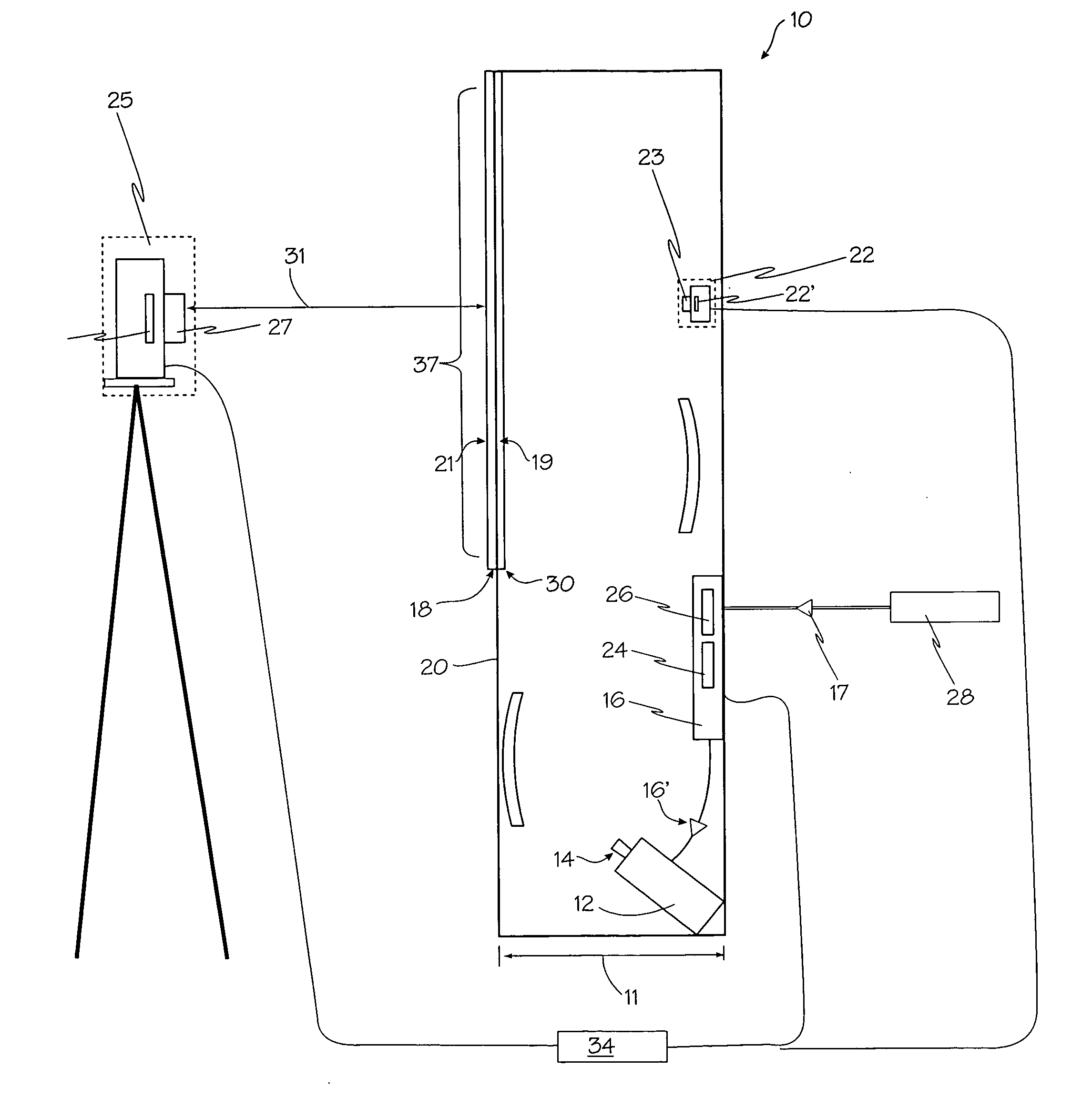
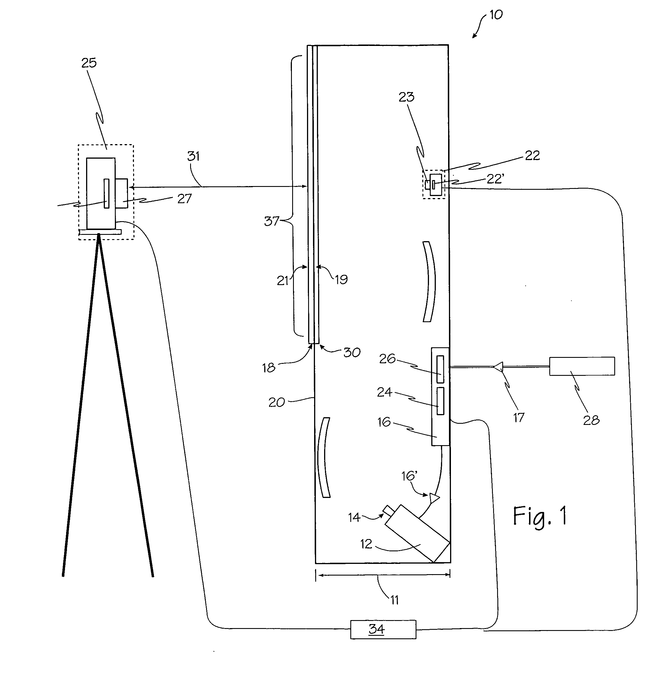
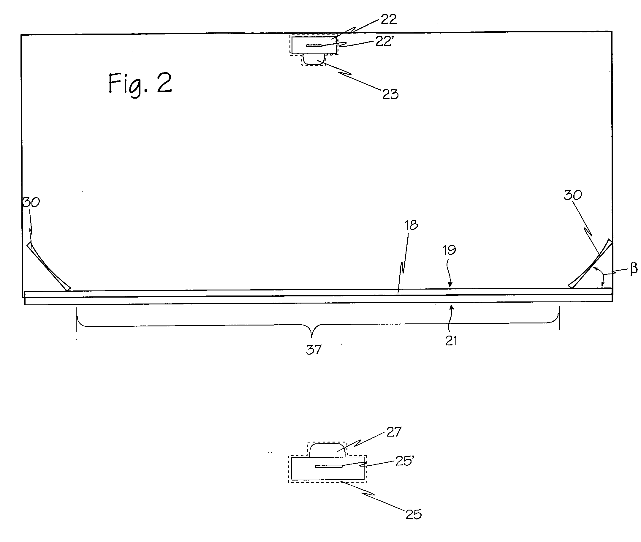
[0021] With reference to FIGS. 1 and 2, rear projection monitor 10 includes projector 12, projection optics 14, control system 16, viewing screen 18, cabinet 20 and low resolution camera 22. Rear projection monitor 10 is of a thin type, meaning that the depth of cabinet 20, represented by distance 11 may be less than fourteen inches. Rear projection monitor 10 may be used, for example, as a television, a home cinema, or the like. Projector 12 is generally mounted below the center horizontal axis of viewing screen 18 and projects upwards, off-axis. Any other suitable orientation of projector 12 may be used. Projector 12 is setup to receive signals from control system 16. The illustrated projector may incorporate a single microdisplay projector for use in a rear projection imaging system and thus may use a transmissive liquid crystal display (LCD) imager, a digital micromirror devices (DMD) imager, or a liquid crystal on silicon (LCOS) imager.

[0022] The microdisplay imager in project...


PUM


Abstract

A video projection calibration technique includes a first camera to view the video display screen from the projector side, and a second camera to view the video display screen from the viewing side. The first camera may be a lower resolution than the second camera. The combination of the two cameras permits the transfer functions of the projection system and the first camera to be characterized and reduced to a warping transform that may be stored by the control system. The presence of the warping transform would permit the lower resolution, first camera to perform image realignment after the video projection system is in use by an end user.

Description

FIELD OF THE INVENTIONS [0001] The inventions described below relate the field of video projection and more specifically to calibration of video projection calibration systems. BACKGROUND OF THE INVENTIONS [0002] It is economically advantageous to use an image warping system with thin-cabinet, large screen microdisplay rear projection monitors (such as televisions and the like that utilize LCOS, LCD, or DMD microdisplay projectors). In order to provide a crisp, distortion free image on a thin-cabinet (small depth) large screen rear projection monitor without the aid of an image warping system, very expensive optics are generally employed. This is driven by the need to produce a large image from a microdisplay imager only a half to one inch (diagonal) across, in the span of a foot or less. Very wide angle lenses are often required to do this. Lower cost large screen rear projection monitors that have lower-cost optics either cannot be thin-cabinet, to avoid distorting the image proje...

Claims


Application Information

Patent Timeline
Patent Type & Authority Applications(United States)
IPC IPC(8): H04N17/02H04N3/26
CPCH04N5/74H04N9/3194
Inventor BOLAS, MARK T.MCDOWALL, IAN E.
Owner FAKESPACE LABS
Why Eureka
Try Eureka