Polarized optical lens

a polarized optical lens and structure technology, applied in the field of polarized optical lens structure improvement, can solve the problems of user inconvenience and user burden, and achieve the effects of diversified color, improved structure of polarized optical lens, and more choices

Inactive Publication Date: 2007-05-24
TONY OPTICAL ENTERPRISES
View PDF3 Cites 11 Cited by
  • Summary
  • Abstract
  • Description
  • Claims
  • Application Information

AI Technical Summary

Benefits of technology

[0008] The major purpose of the current invention is to provide an improvement structure for polarized optical lens, it has diversified color and lets the users have more choices and enhance their purchase desire. Another purpose of the current invention is to provide an improvement structure for polarized optical lens, it is thinner and lighter, it effectively reduces manufacturing and material cost, it also lets the user feel more comfortable while wearing it.

Problems solved by technology

In the prior art polarized lens, two optical lenses (A) with certain curvature are used, adhesive is coated in between them and pressure is used to paste polarized piece (B), a polarized optical piece is thus formed, this is as shown in FIG. 1, however, the prior art polarized optical lens is too thick and weighs too much, it creates great inconvenience to the user.
Light weight is always the trend for glasses, therefore, the prior art polarized optical lens then gradually becomes obsolete, meanwhile, the production cost can not be lowered due to the use of two glass lens in the prior art polarized optical lens, it creates great burden to the user.

Method used


Image

  • Polarized optical lens
  • Polarized optical lens
  • Polarized optical lens

Examples


Embodiment Construction

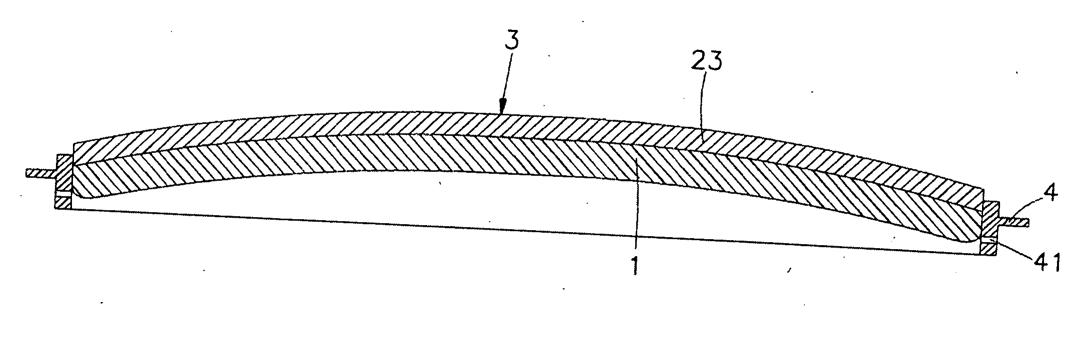
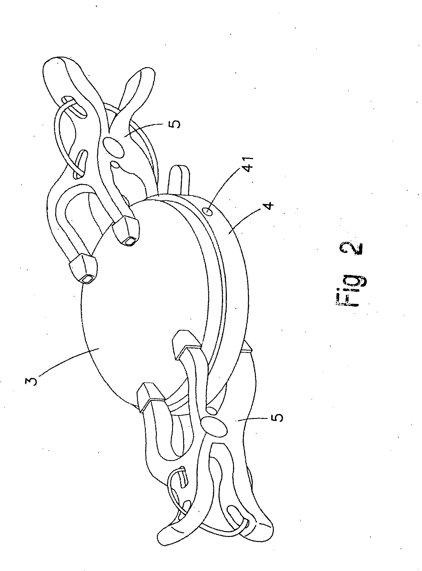
[0012] Please refer to the attached drawings, the structural improvement of the polarized optical lens of the current invention is as shown in FIGS. 2 and 3, the structural improvement of the polarized optical lens comprising of an optical lens (1) of certain curvature, an polarized optical thin film (23).

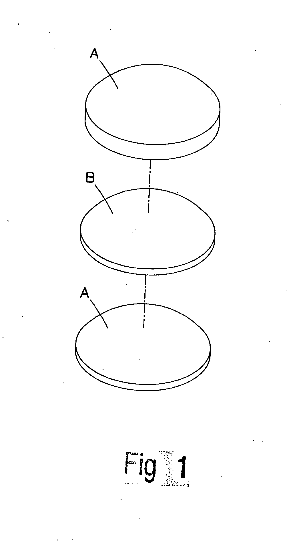
[0013] For the manufacturing method of the current invention, a polarized piece (2) comprising of cellulose protective film (21), adhesive (22) and polarized film (23) is first formed, its layer structure from top to bottom is in such order as: cellulose protective film (21), polarized thin film (23), adhesive (22) and cellulose protective film (21), the polarized piece is then placed in a mold for pressing to a curvature similar to optical lens (1), then the cellulose protective film (21) of polarized piece (2) is peeled off, the polarized film (23) can be placed on the optical mold of plastic injected machine, adhesive (22) and pressure is used to paste it to the plastic injecte...


PUM

PropertyMeasurementUnit
coloraaaaaaaaaa
structureaaaaaaaaaa
hardnessaaaaaaaaaa

Abstract

This invention relates to a structure improvement for a polarized optical lens, it comprising of an optical lens of certain curvature and a polarized piece, wherein the polarized piece is made up of cellulose protective film, adhesive and polarized thin film, it is pressed to matched curvature as injected and plasticized optical lens, then the cellulose protective film of the polarized piece is peeled off, through the use of injection and plasticization principle, polarized thin film is combined and pasted to the inner surface or outer surface of the optical lens, then this synthesized lens is placed in the ring of an optical mold, light adjustment and color change liquid colophony is then injected into through a through-hole in the ring, and through the clamping of synthesized lens and light adjustment and color change liquid colophony, the whole set then solidifies and forms a shape so that the diversified functions and light adjustment and color change function of the product is achieved, meanwhile, the optical lens possesses polarization effect and reaches the world class grade lens level, therefore, when it is worn outdoors, dark and light change will be created due to the absorption of UV light, the user can feel more comfortable, and the optical lens thus possesses more diversified color.

Description

BACKGROUND OF THE INVENTION [0001] 1. Field of the Invention [0002] This invention relates to a structure improvement for a polarized optical lens, it more specifically relates to a polarized optical lens which is a pressing combination of optical lens and polarized thin film, meanwhile, through a through-hole of a ring, light adjusting and color changing liquid colophony is injected into, then it is solidified, a single polarized optical lens can thus have diversified lens color, it can generate dark and light color change at different ultraviolet value, it not only lets the user feel more comfortable while wearing it, but also lets the optical lens have more diversified color. [0003] 2. Description of the Prior Art [0004] People acquires most of the message through the eye, therefore, when someone's vision has trouble, for example, myopia, presbyopia, hyperopia, astigmatism, etc., all have to be corrected by glasses, therefore, optical lenses is strongly related to vision quality,...

Claims


Application Information

Patent Timeline
Patent Type & Authority Applications(United States)
IPC IPC(8): G02C7/10
CPCG02C7/12G02C7/105G02C2202/16
Inventor LIN, JUEI-TSE
Owner TONY OPTICAL ENTERPRISES
Why Eureka
Try Eureka