
High bay inductive lighting efficiency I

a technology of inductive lighting and high bay lighting, which is applied in the direction of lighting and heating apparatus, lighting support devices, lighting source combinations, etc., can solve the problems of inefficient use of light bulbs in these lighting installations and high maintenance costs of these bulbs, so as to improve cosmetics, reduce height, and improve efficiency. effect of

Inactive Publication Date: 2007-05-24
SANDOVAL RUBEN
View PDF24 Cites 27 Cited by
  • Summary
  • Abstract
  • Description
  • Claims
  • Application Information

AI Technical Summary

Benefits of technology

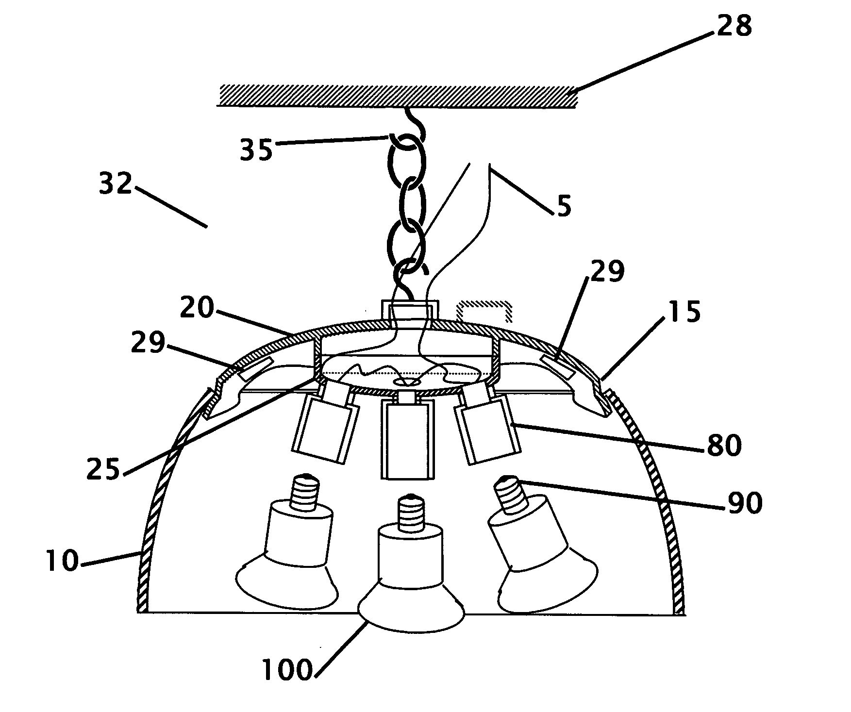
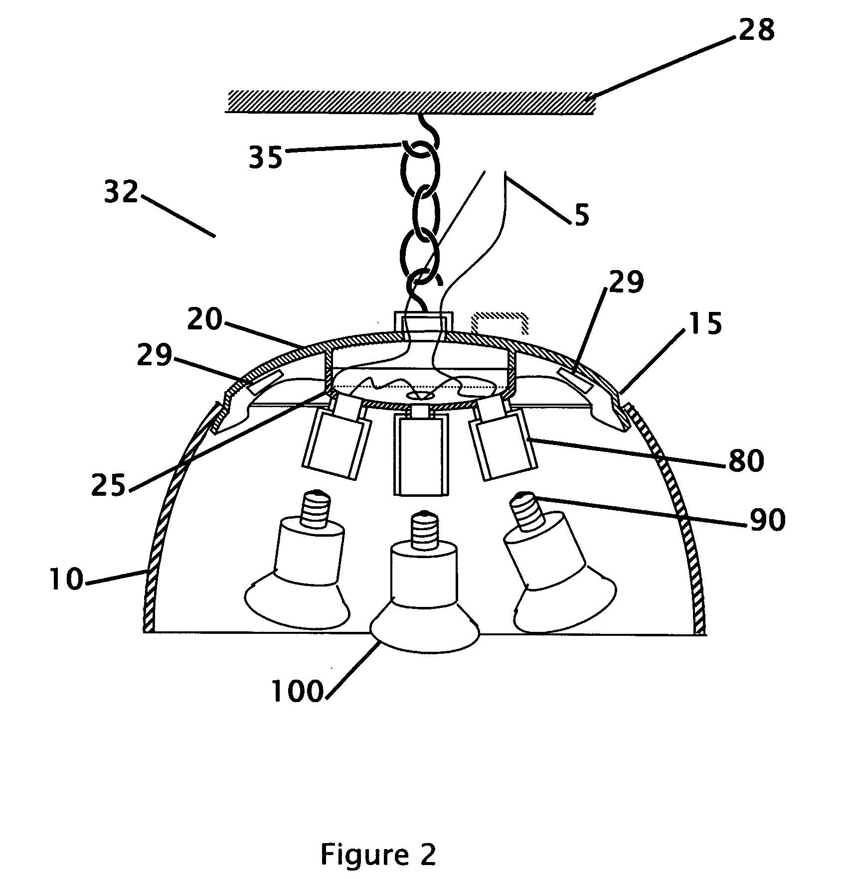
[0009] A standard 100-watt incandescent bulb uses 100 watts of energy, a fluorescent light (or inductive light) bulb that provides the same amount of light only requires about 20 to 25 watts of energy. Fluorescent light consume 45 to 50% less energy than a standard incandescent light bulb. The light from fluorescent light is similar or superior to the light from an incandescent light, and can be tinted to provide different shades to simulate other lighting sources. The fixture requires the installation onto the rafters or ceiling of the building where it is installed to produce light that is emitted above and below the lighting fixture as well as out the sides of the lighting fixture. A candelabra lighting fixture is then snapped into an existing dome. A reflector dome located in the lighting fixture helps to focus the lighting down to where the light is needed. An inductive light source provides an improved lighting source 20 to 30% brighter than standard fluorescent bulbs with increased efficiency and 50% longer bulb life.
[0010] A warehouse typically uses 450-465 watt incandescent, halogen or similar light bulb and ballast system. The proposed invention replaces the single 400-watt light bulb with five fluorescent or inductive self ballasting fluorescent lights providing the same or more illumination. The standard warehouse light uses 450-465 watts to produce the light. The five self ballasting fluorescent lights only require 240 to 250 watts of energy. An inductive light source only requires 200 to 220 watts of energy to produce the same amount of illumination, saving 170 to 255 watts of energy that would be spent in heat. A 400 watt metal halide light operates at 1750 degrees of heat, where a fluorescent or inductive lamp operates at 190 to 210 degrees. Inside an air conditioned building the 170 to 255 watts of heat would need to be cooled with the air conditioning system within the building. The savings come from three places, first the more efficient lights, second from air conditioning costs and third, from less maintenance costs. In addition, there can be safety benefits from less ultraviolet rays, and for less chance that the fluorescent bulbs will explode. Inductive lighting provides improved efficiency and savings where a standard warehouse light uses 450-465 watts to produce the light. One to three inductive lights may require as little as 200 watts of energy to produce more light than a standard warehouse light and will provide saving of 250 to 265 watts of energy and 1500 degrees of heat would be spent in heat. Inside an air conditioned building the 1750 degrees of heat would need to be cooled with the air conditioning system within the building. The savings come from three places, first the more efficient lights, and second from air conditioning costs, induction lamps further reduce re-lamping costs by 500%, or mounted separately to 600% reduce, and third the maintenance and government imposed hazardous waste disposal costs.
[0012] The lighting fixture can be separated from the ballast box and mounted or hung separately where the installation calls for reducing the height by as much as 40%. This allows improved cosmetics, height without compromising the efficiency or operation of the fixture. The components of the fixture are designed to allow the parts to be connected or separated in the field without requiring additional components.
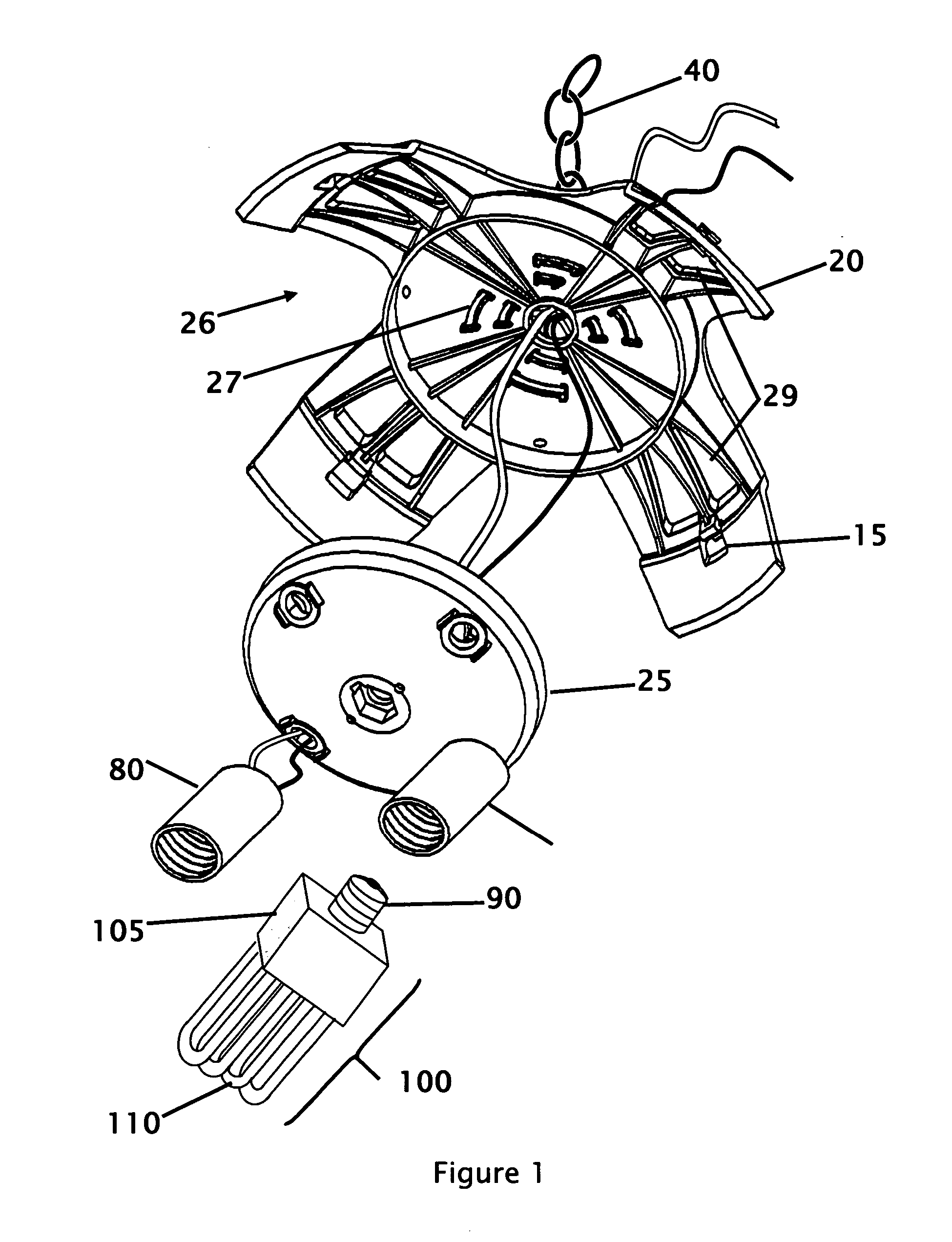
[0013] The construction of the lighting fixture consists of a joist or ceiling mounting system where the fixture can be suspended from a chain or hard mounted. The electrical wires from the building are wired into the top of the fixture, where it is wired into each of the sockets in the candelabra fixture. The candelabra arrangement consists of at least two bulb sockets that extend from a base structure. The bulbs can extend from fixed or flexible arms, goosenecks. The bulbs can be threaded into multiple sockets from the base. The sockets can be wired in series, parallel or combined series and parallel arrangement that keeps the voltage to a safe level for the lights screwed into the sockets.
[0014] A reflector or dome can be integrated onto the lighting fixture to eliminate the hanging fixture normally associated with high bay lighting. The reflector or dome is retained on the lighting fixture with retaining snap locks and gravity. The reflector focuses light down from the fixture, while a dome helps to defuse the light and provide lighting that is emitted up, down and out the sides of the lighting fixture.
[0015] One problem with placing a toroidal lighting element within the dome is the shadow that exists from the light of the lighting element blocking the light emitted from the back side of the lighting element. Different light diameters and different dimensions will yield varying reflective angles that will reflect the light from behind the lighting element to the front of the lighting fixture to eliminate the shadow that can be appear under the lighting dome. The internal geometry to minimize or eliminate the shadow. The proposed lighting apparatus minimizes the blocked light by reflecting light around the toroidal, inductive lighting element.

Problems solved by technology

Most light bulbs used in these lighting installations are inefficient, and a portion of the energy used in these lights is expended in heat.
The maintenance cost of these bulbs is also high due to the cost of government imposed lamp disposal fee, the short lifespan and the rapid degradation of 30 to 40% after a year.

Method used


Image

  • High bay inductive lighting efficiency I
  • High bay inductive lighting efficiency I
  • High bay inductive lighting efficiency I

Examples


Embodiment Construction

[0029] Referring first to FIG. 1 that shows an isometric exploded view of the lighting fixture. The fixture works with store, warehouse or industrial lighting systems. The lighting fixture is intended for use as high bay, low bay lighting or similar lighting fixture where incandescent, halogen, sodium, metal halide, mercury vapor or other less efficient light bulbs are used. Four tabs 15 are arranged on the upper housing of the fixture 20 for locating and retaining a dome or reflector. Four tabs (one on each wing) are shown for locating the dome. But more or less tabs can be used. The figures show the upper housing with four tabs used to retain the dome or reflector, but as few as two or three tabs, or more than four tabs are contemplated with other designs. It is also contemplated that a ridge can be incorporated into the housing to retain the dome without any tabs. The bottom fixture reflector helps to improve the efficiency of the lighting by directing light downward. The reflect...


PUM


Abstract

A lighting fixture where the lighting fixture uses inductive lighting technology or self ballasting lighting elements with one or a plethora of efficient light elements. The lighting fixture is used where high bay or low bay lighting may be used, but incorporates multiple light sources to provide an equivalent light intensity. The multiple light sources can be inductive or multiple fluorescent, LED or other efficient light sources to provide a less expensive cost of operation and installation. The higher efficiency lights could be standard socket type fluorescent or inductive light bulbs that are easily available. The higher efficiency lights will also create less heat that will further reduce the air conditioning or cooling costs for the building. An integrated ballast box with reflector dome retainer is also shown for use with inductive or other lighting that further includes a retaining mechanism for the dome.

Description

FIELD OF THE INVENTION [0001] The present invention relates generally to a bay lighting fixture using multiple self-ballasting bulbs or inductive light elements. More specifically the invention is designed to replace a high-bay, low-bay warehouse or similar lighting fixture. The invention may include a hanging system that allows the entire assembly to be wired into a new or existing building and supply self ballasting lights, or ballast box and the dome. This fixture uses multiple high efficiency standard fluorescent single or multiple inductive lighting or other high efficiency light bulbs or lamps. An integrated ballast box with reflector dome retainer is also disclosed for use with inductive or other lighting where the housing includes a retaining mechanism for the dome. BACKGROUND OF THE INVENTION [0002] Lighting is used to provide light when it is dark or to provide supplemental lighting for a dark area. Often in large buildings, overhead lighting is provided from lights placed...

Claims


Application Information

Patent Timeline
IPC IPC(8): F21V23/02
CPCF21S8/06F21V15/01F21V23/026H01J65/048F21Y2103/02F21Y2103/025F21Y2113/00F21Y2103/30F21Y2103/37
Inventor RUBEN, SANDOVAL
Owner SANDOVAL RUBEN
Learn More