Adaptive image processing and display for digital and computed radiography images

a computed radiography and image technology, applied in the field of image processing and display of digital images, can solve the problems of compromising the health and safety of patients, difficult for doctors, technicians, or other medical providers to read and interpret, and inconsistent quality of diagnostic images

Active Publication Date: 2007-05-24
GENERAL ELECTRIC CO
View PDF21 Cites 13 Cited by
  • Summary
  • Abstract
  • Description
  • Claims
  • Application Information

AI Technical Summary

Problems solved by technology

The diagnostic image is typically of inconsistent quality as initially scanned.
Inconsistent image quality makes it difficult for doctors, technicians, or other medical providers to read and interpret.
Furthermore, as a result of the inconsistent quality of images, doctors, technicians, and other medical providers may misdiagnose medical conditions, thereby compromising the health and safety of their patients.
There are several disadvantages to improving image quality by manually selecting or adjusting an appropriate image processing parameter based on an estimation of patient size or thickness by examination or measurement.
First, manually selecting or adjusting an image processing parameter based on an estimation of patient size or thickness, whether by visual examination or measurement, for example, is not accurate.
An operator or technician could easily make a mistake, either in estimating patient size or thickness or in selecting or adjusting an appropriate image processing parameter.
Consequently, an operator or technician could easily select the same image processing parameter for two patients of vastly different sizes or thicknesses, which would not be appropriate.
Therefore, a single image processing parameter may not be appropriate even for an individual patient.
Second, manually selecting or adjusting an image processing parameter based on an estimation of patient size or thickness, whether by examination or measurement, for example, is not automatic.
Manually examining or measuring each patient prior to imaging takes more time, thereby limiting the number of patients that can be imaged in a given time period.
Consequently, manually estimating patient sizes or thicknesses and manually selecting or adjusting imag

Method used


Image

  • Adaptive image processing and display for digital and computed radiography images
  • Adaptive image processing and display for digital and computed radiography images
  • Adaptive image processing and display for digital and computed radiography images

Examples


Embodiment Construction

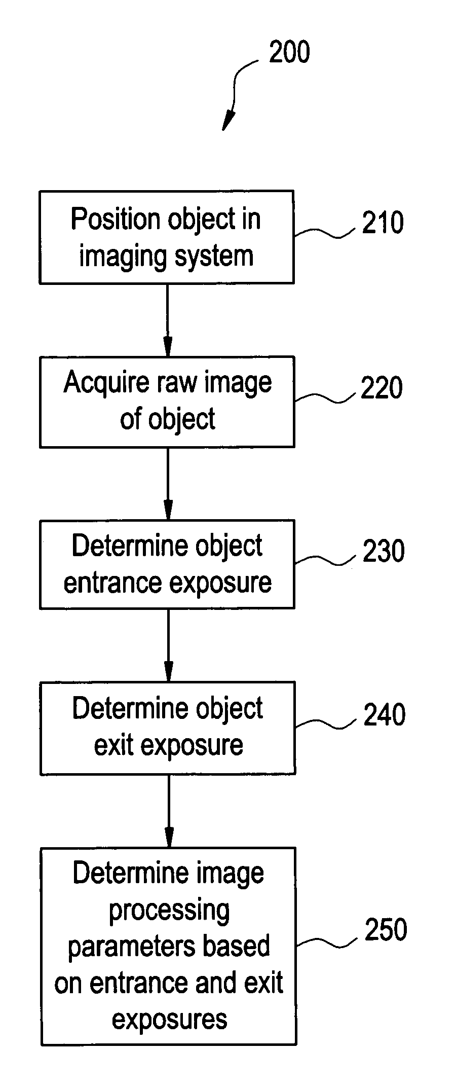
[0023]FIG. 1 illustrates an imaging system 100 for adaptive image processing and / or display, according to at least one embodiment of the presently described technology. The imaging system 100 includes an object 110, an energy source 120, and an energy sensor 130. The imaging system 100 may also include an image processor 140 (not shown) and an image display 150 (not shown). The sensor or detector 130 may include a plurality of detector elements (not shown).

[0024] The components of the imaging system 100 may be implemented in software, hardware, and / or firmware, for example. The components of the imaging system 100 may be implanted separately and / or integrated in various forms, for example.

[0025] The object 110, such as a patient or selected area or anatomy of the patient, may be positioned or located in the imaging system 100. More particularly, the object 110 may be positioned or located between the energy source 120 and the energy sensor 130. The energy source 120 produces energ...


PUM


Abstract

The presently described technology provides a method for adaptive image processing. The image processing method includes determining an entrance exposure of an object, determining an exit exposure of the object, and determining one or more image processing parameters based at least in part on the entrance and exit exposures. The presently described technology also provides a method for adaptive image display. The image display method includes determining an entrance exposure of an object, determining an exit exposure of the object, and displaying an attenuation map based at least in part on the entrance and exit exposures.

Description

BACKGROUND OF THE INVENTION [0001] The presently described technology relates generally to image processing and display for digital images. More specifically, the presently described technology relates to adaptive image processing and display for digital and computed radiography images. [0002] X-ray imaging has long been an accepted medical diagnostic tool. X-ray imaging systems are commonly used to capture, as examples, thoracic, cervical, spinal, cranial, and abdominal images that often include information necessary for a doctor to make an accurate diagnosis. X-ray imaging systems typically include an x-ray source and an x-ray sensor. When having a thoracic x-ray image taken, for example, a patient stands with his or her chest against the x-ray source at an appropriate height. X-rays produced by the source travel through the patient's chest, and the x-ray sensor then detects the x-ray energy generated by the source and attenuated to various degrees by different parts of the body. ...

Claims


Application Information

Patent Timeline
IPC IPC(8): G06K9/00
CPCA61B6/00A61B6/544A61B6/4233
Inventor JABRI, KADRI N.
Owner GENERAL ELECTRIC CO
Why Eureka
Try Eureka