Bifurcation stent delivery system

a stent and stent technology, applied in the field of implantable medical devices, can solve the problems of difficult rotation of the stent delivery system to a site within the body, and achieve the effects of reducing the profile improving the trackability of the stent delivery system, and simplifying the placement of the sten

Inactive Publication Date: 2007-05-24
BOSTON SCI SCIMED INC
View PDF26 Cites 11 Cited by
  • Summary
  • Abstract
  • Description
  • Claims
  • Application Information

AI Technical Summary

Benefits of technology

[0014] The invention contemplates a new apparatus and method that simplifies placement of a stent at the bifurcation of a vessel. The invention results in a reduced stent delivery system profile. The present system may improve trackability of the stent delivery system.

Problems solved by technology

Rotating a stent delivery system delivered to a site within the body is difficult.

Method used


Image

  • Bifurcation stent delivery system
  • Bifurcation stent delivery system
  • Bifurcation stent delivery system

Examples


Embodiment Construction

[0036] While this invention may be embodied in many different forms, there are described in detail herein specific preferred embodiments of the invention. This description is an exemplification of the principles of the invention and is not intended to limit the invention to the particular embodiments illustrated.

[0037] For the purposes of this disclosure, like reference numerals in the figures shall refer to like features unless otherwise indicated.

[0038] Depicted in the figures are various aspects of the invention. Elements depicted in one figure may be combined with, and / or substituted for, elements depicted in another figure as desired.

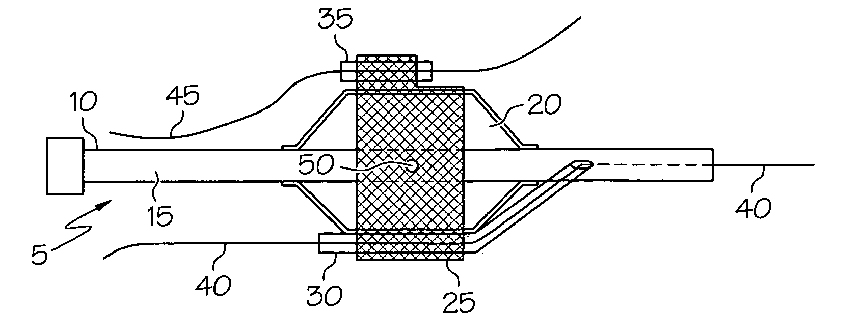
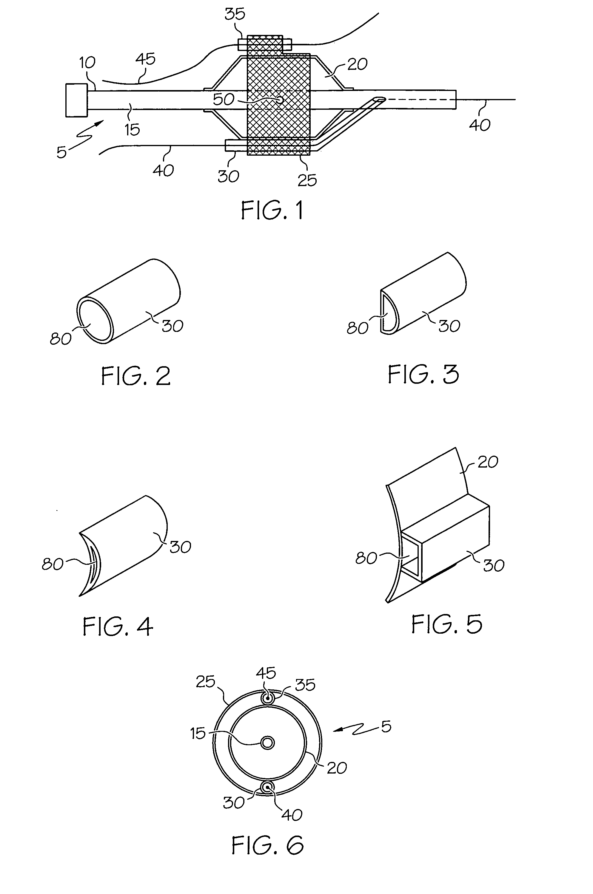
[0039] Referring now to the drawings, wherein the showings are for the purposes of illustrating the preferred embodiments of the invention and not for purposes of limiting same, FIG. 1 shows a stent delivery system or assembly 5. Assembly 5 shows a catheter 10 comprising catheter shaft 15. Disposed about catheter shaft 15 is balloon 20. Disposed...


PUM


Abstract

A catheter assembly includes a catheter, a balloon, a plurality of guidewire housings, and a stent. The stent is disposed about the balloon. At least a portion of each of the guidewire housings is positioned between the stent and the balloon.

Description

CROSS-REFERENCE TO RELATED APPLICATIONS [0001] Not Applicable STATEMENT REGARDING FEDERALLY SPONSORED RESEARCH [0002] Not Applicable BACKGROUND OF THE INVENTION [0003] 1. Field of the Invention [0004] In some embodiments this invention relates to implantable medical devices, their manufacture, and methods of use. Some embodiments are directed to delivery systems, such as catheter systems of all types, which are utilized in the delivery of such devices. [0005] 2. Description of the Related Art [0006] A stent is a medical device introduced to a body lumen and is well known in the art. Typically, a stent is implanted in a blood vessel at the site of a stenosis or aneurysm endoluminally, i.e. by so-called “minimally invasive techniques” in which the stent in a radially reduced configuration, optionally restrained in a radially compressed configuration by a sheath and / or catheter, is delivered by a stent delivery system or “introducer” to the site where it is required. The introducer may...

Claims


Application Information

Patent Timeline
Patent Type & Authority Applications(United States)
IPC IPC(8): A61F2/06
CPCA61F2/856A61F2/954A61F2/958A61F2002/065
Inventor WEBER, JANJAGGER, KARL A.EIDENSCHINK, TRACEE
Owner BOSTON SCI SCIMED INC
Why Eureka
Try Eureka