Controller

a controller and control panel technology, applied in the field of controllers, can solve the problems that the conventional controller cannot meet such needs, and achieve the effect of slowing down the flow rate and reducing the flow of high pressure gas

Inactive Publication Date: 2007-05-31
FUJIKIN INC
View PDF10 Cites 6 Cited by
  • Summary
  • Abstract
  • Description
  • Claims
  • Application Information

AI Technical Summary

Benefits of technology

[0014] According to the controller of the present invention, a power transmitting means for amplifying the force applied on the operating shaft and transmitting to the valve rod, and a slow start means for slowly moving ...

Problems solved by technology

A conventional controller ...

Method used


Image

  • Controller
  • Controller
  • Controller

Examples


Embodiment Construction

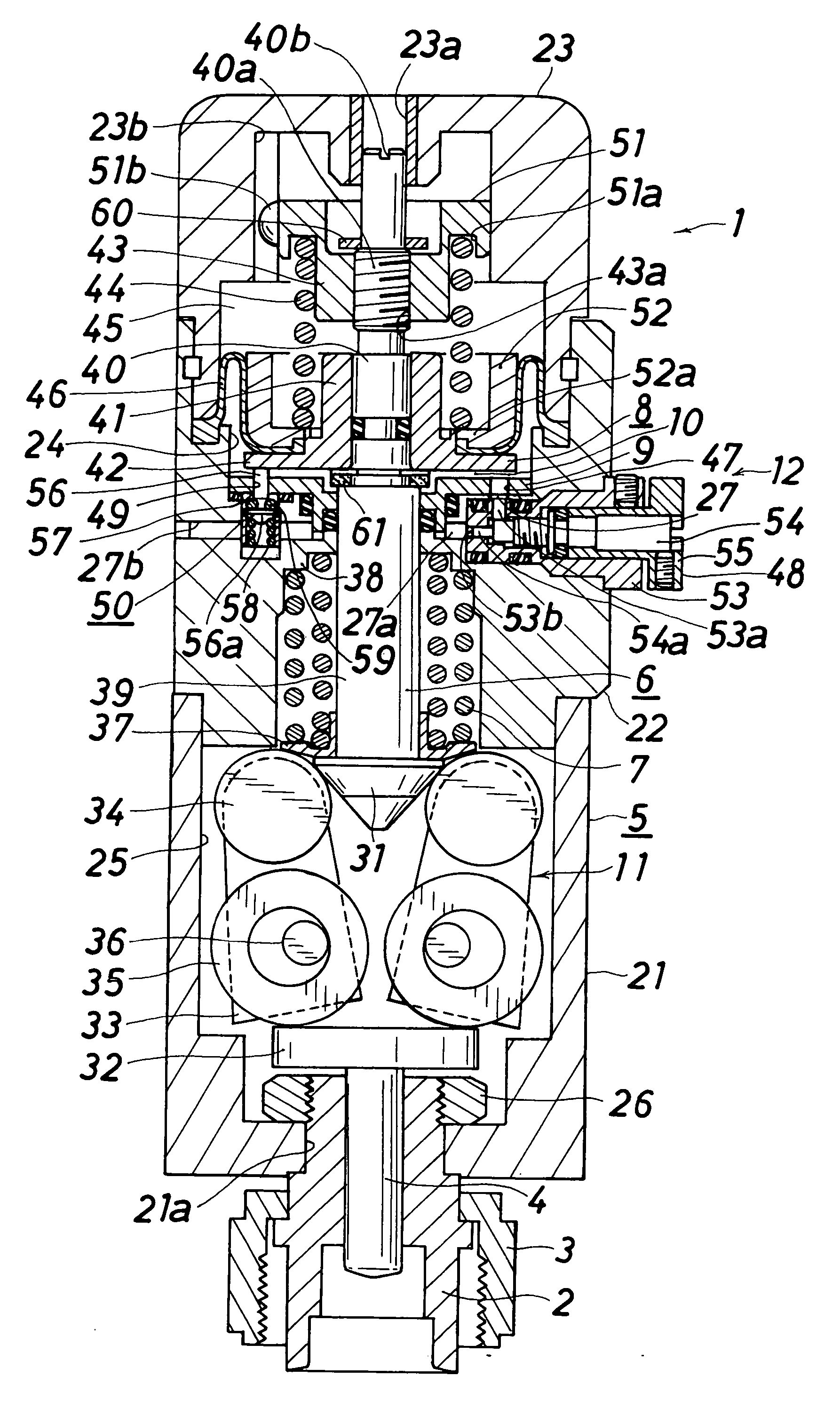
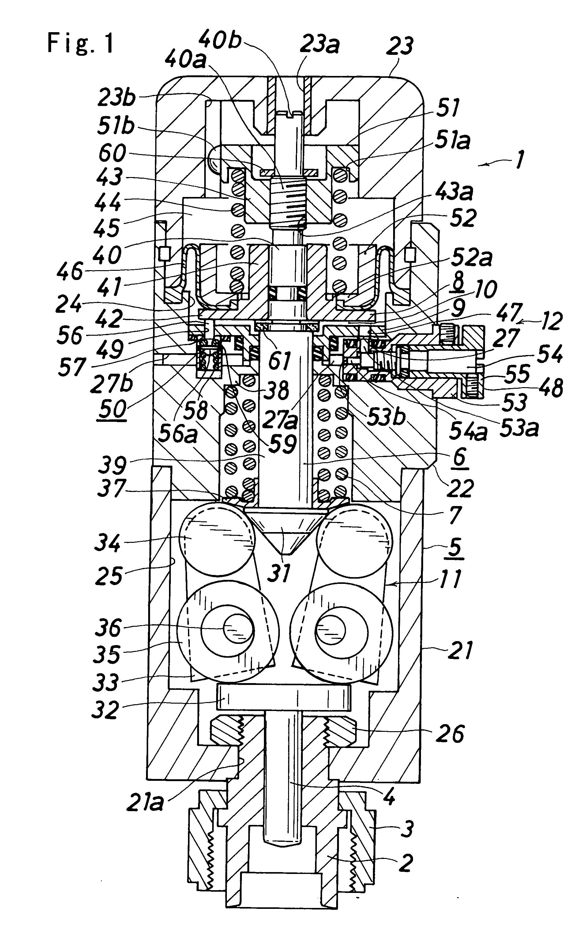
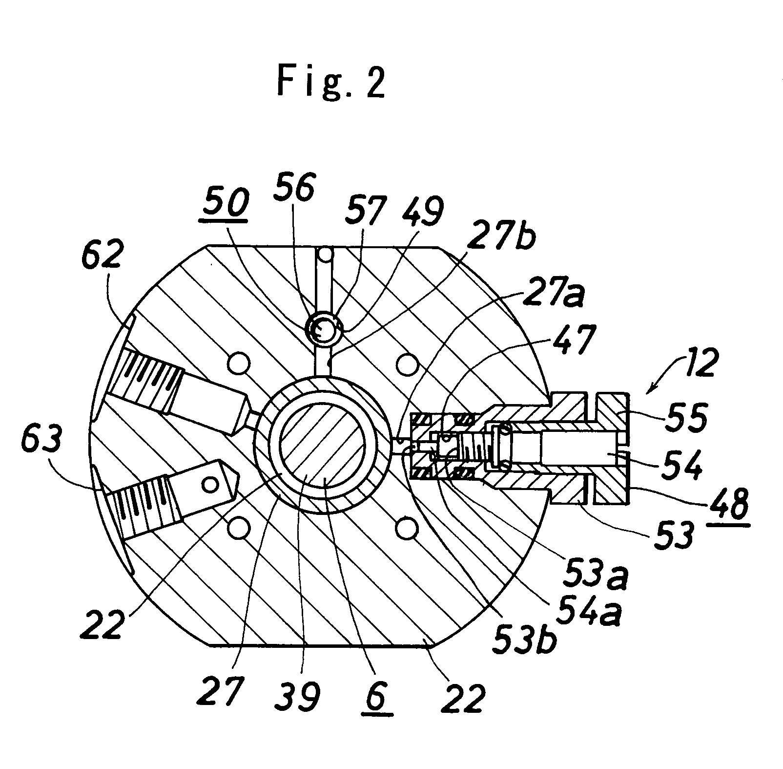
[0017] The embodiment of the present invention will now be described with reference to the drawings. In the following description, up and down, as well as left and right of FIG. 1 are respectively referred to as up and down and left and right.

[0018] As shown in FIGS. 1 and 2, the controller (1) includes a cylindrical bonnet (2) attached by a cap nut (3) to a valve main body (not shown) formed with a fluid passage; a valve rod (4) that is inserted into the bonnet (2) and that moves up and down in a reciprocating manner; a casing (5) fixed to the upper end of the bonnet (2); an operating shaft (6) arranged in the casing (5) in a freely up and down moving manner; a biasing means (7) for biasing the operating shaft (6) downward; a pressure chamber (10), formed between the piston (8) arranged at the operating shaft (6) and a partition plate (9) arranged below the piston and fixed to the casing, for moving the operating shaft (6) upward when the operation gas is introduced; a power trans...


PUM


Abstract

A controller comprises power transmitting means (11) for amplifying the force applied on the operating shaft (6) and transmitting to the valve rod (4); and a slow start means (12) for slowly moving the operating shaft (6) upward are arranged. The slow start means (12) includes a piston (8) that moves up and down with respect to the operating shaft (6); a pressure spring (44), arranged between a pressure spring receiver (43) arranged at the operating shaft. (6) and the piston (8); a constantly opened communication passage (47) and an auxiliary communication passage (49) for communicating the pressure chamber (10) and the operation gas introducing chamber (27); a flow adjusting valve (48) provided in the constantly opened communication passage (47); and an open-close valve (50), arranged in the auxiliary communication passage (49), for opening the communication passage (49) when the piston (8) is at the lower most position and closing the communication passage (49) when raised from the lower most position by a predetermined distance and reaching the auxiliary communication shut off position.

Description

TECHNICAL FIELD [0001] The present invention relates to controllers, more specifically, to a controller suitable when using a high pressure fluid. BACKGROUND ART [0002] As a controller suitable when using a high pressure fluid, a controller is disclosed in patent article 1 (Japanese Laid-Open Patent Publication No. H07-139648) that includes a valve main body in which a fluid passage between a valve disc and a valve ring opens and closes with the up and down movement in a reciprocating manner of a valve rod; a casing fixed to an upper part of the valve main body; an operating shaft arranged at the upper section in the casing in a freely up and down movable manner; a driving means for moving the operating shaft up and down; a power transmitting means, arranged at the lower section in the casing, for amplifying the force applied on the operating shaft and transmitting to the valve rod; a biasing means for biasing the operating shaft downward; and a pressure chamber, formed between a pi...

Claims


Application Information

Patent Timeline
IPC IPC(8): F16K31/12F16K31/122F16K31/163F16K31/44
CPCF16K31/1262Y10T74/18992F16K31/165F16K31/163F16K31/122F16K31/60
Inventor SHINOHARA, TSUTOMUYAMAJI, MICHIO
Owner FUJIKIN INC
Why Eureka
Try Eureka