Molded article production method and molded article

a technology of molded article and production method, which is applied in the field of molded article production method and molded article, can solve the problems of insufficient expansion of thermally expandable material, detrimental to the air tightness between the resin part and the main body, and the inability to sufficiently compress the injection molding of the resin part with the sealant, etc., and achieves cost-effective effects

Active Publication Date: 2007-05-31
TOYOTA JIDOSHA KK +1
View PDF20 Cites 4 Cited by
  • Summary
  • Abstract
  • Description
  • Claims
  • Application Information

AI Technical Summary

Benefits of technology

[0013] The present invention provides the required level of air-tightness by using an expanded foam sealant instead of expanding the sealant by using the heat of injected molten resin as in the technique disclosed in Japanese Patent Application Publication No. JP-A-10-15985. In accordance with the present invention, the foam sealant is compressed before or during the injection molding process. No insufficient expanding of the foam sealant occurs in the present invention. If injection molding is conducted when the foam sealant is compressed before or during the injection molding process, the compressed sealant is restored to compensate the shrinkage of the molten resin, which may occur in the solidification of the latter. The foam sealant remains compressed even if the molten resin shrinks during its solidification. Accordingly, it is possible to ensure an increased air-tightness by placing the compressed foam sealant between the solidified resin (resin part) and the main body part.
[0014] In accordance with the present invention, it is possible to positively assure the air-tightness at the surface boundary between the main body part and the resin part without any additional processing, e.g., reheating the molded article. Therefore, there is no need for a step for making sure the air-tightness maintained at the surface boundary after the resin part has been injection-molded. This makes it possible to cost-effectively provide a molded article in which the resin part is injection-molded to the main body part, while ensuring the air-tightness at the surface boundary between the main body part and the resin part.

Problems solved by technology

However, since conventionally used sealants such as the O-ring exhibit high repulsion and low compressibility, it is impossible to perform the injection molding of the resin part with the sealants sufficiently compressed.
Thus, due to the shrinkage occurring during cooling and solidification of the molten resin, a gap may be created at the surface boundary between the resin part and the sealant or between the sealant and the main body part, thus detrimentally affecting the air-tightness between the resin part and the main body part.
However, in the described technique, the expansion of the thermally expandable material may sometimes be insufficiently in the case where the thermally expandable sealant is attached around the target portion of the main body part to which the resin part is to be injection-molded and then the thermally expandable sealant is expanded by the heat of the molten resin in the injection molding process.
For example, if the resin part to be molded has a relatively small volume, the molten resin may fail to carry enough heat to sufficiently expand the sealant.
Insufficient expansion of the sealant makes it impossible to attain the required air-tightness.
However, this technique requires an additional processing step of reheating the molded article.

Method used


Image

  • Molded article production method and molded article
  • Molded article production method and molded article
  • Molded article production method and molded article

Examples


first embodiment

[0053] Referring now to FIGS. 1A-1C, general description will be given to a connector case (molded article) 10 produced by using a method in accordance with a first embodiment of the present invention.

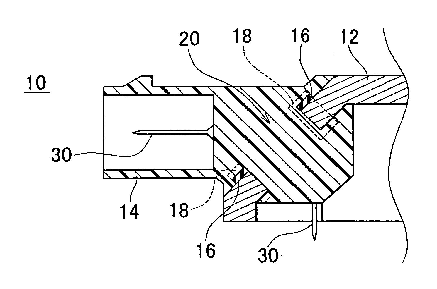
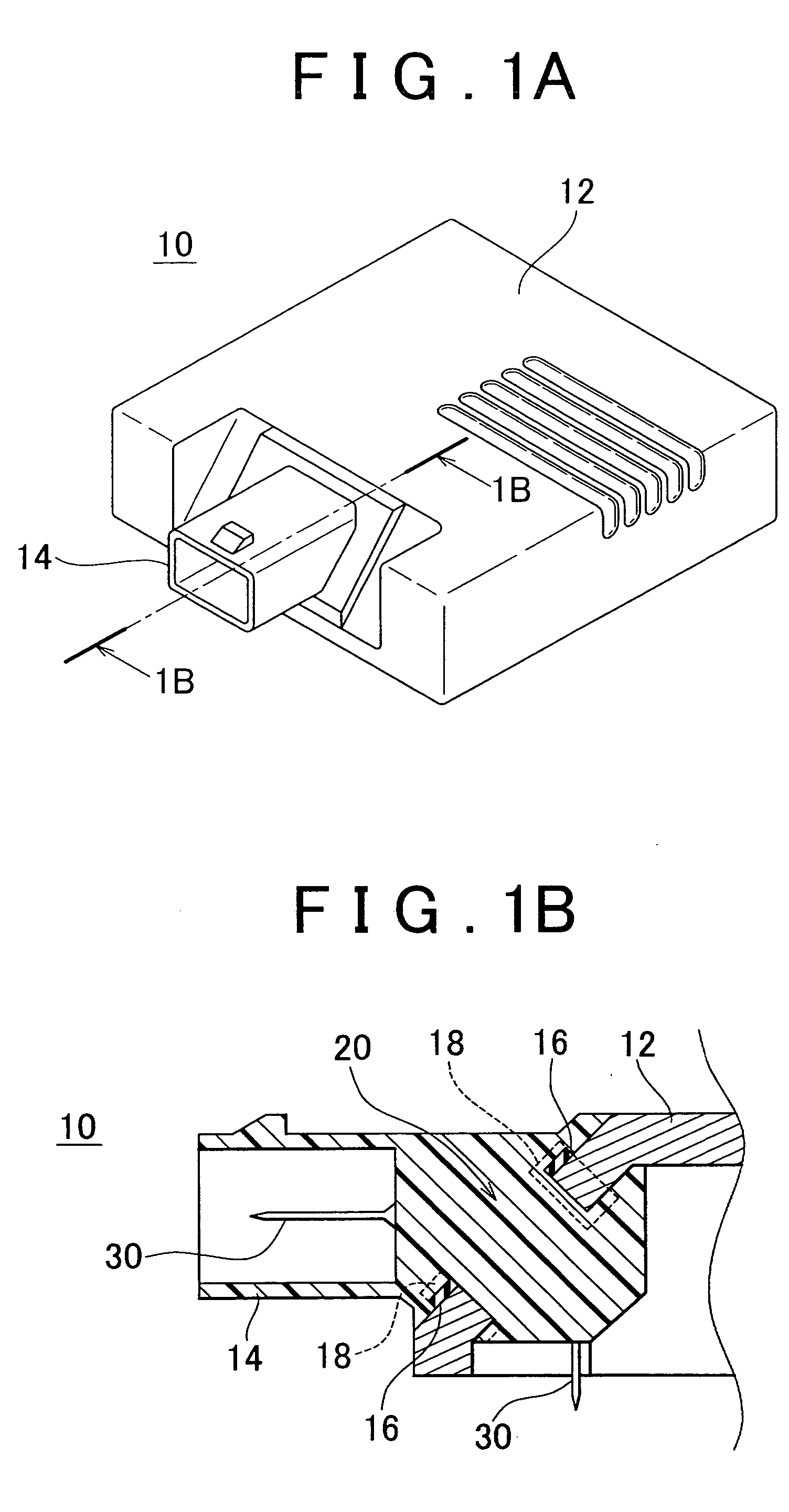
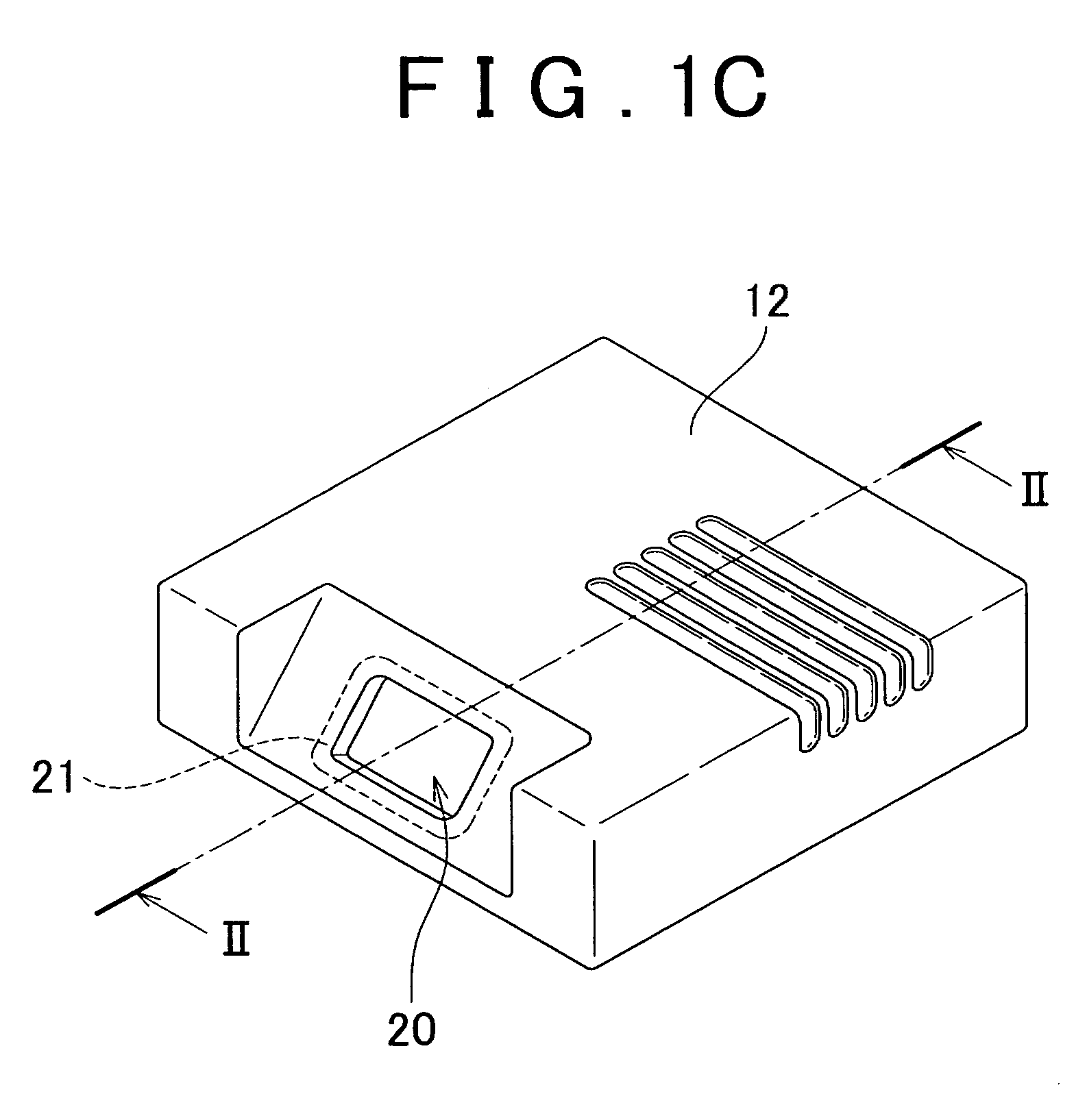
[0054]FIG. 1A is a schematic perspective view showing a connector case 10 produced by using the method in accordance with the first embodiment of the present invention, FIG. 1B is an enlarged vertical cross-sectional view taken along line 1B-1B in FIG. 1A to illustrate the surroundings of a connector part 14, and FIG. 1C is a schematic perspective view depicting a main body part 12 of the connector case 10. The first embodiment is directed to a method for producing a connector case 10 in which a resin-made connector part (resin part) 14 is molded in an opening 20 of a metallic main body part 12 by using an injection molding process.

[0055] As shown in FIG. 1A, the resin-made connector part 14 is molded onto the main body part 12 through an injection molding process. As is apparent in ...

second embodiment

[0082] Next, a second embodiment of the present invention will be described with reference to FIGS. 9 and 10. FIG. 9 shows a closed mold in the second embodiment and corresponds to FIG. 6, which was referred to when making description on the molded article production method of the first embodiment. FIG. 10 illustrates the cavity of the mold when the resin is injected in the second embodiment and corresponds to FIG. 7, which was referred to when making description on the molded article production method of the first embodiment. In the second embodiment, the retainer 18 is not attached to the main body part 12. Thus, the main body part 12 of the condition as shown in FIG. 2 is disposed on the bottom mold 22 and, subsequently, the steps of the first embodiment illustrated in FIGS. 4 and 5 are carried out.

[0083] In accordance with the second embodiment, the top mold 24b includes a compression member 50a that can be moved within the cavity 36 in the thickness direction of the foam seala...

third embodiment

[0089] Next, a method of producing a molded article in accordance with a third embodiment of the present invention will be described. In the third embodiment the foam sealant 16 is compressed by the pressure of resin acting in the injection process of the molten resin. According to this method, the foam sealant 16 is attached to the external surface of the peripheral portion 21 around the opening 20 of the main body part 12, as shown in FIG. 2 and placed within the mold. Subsequent steps are the same as the steps described earlier in connection with FIGS. 4 through 8, except that the retainer 18 is not used. In the following, the third embodiment will be described with reference to FIGS. 4 through 8 on the premise that the retainer 18 is not attached to the main body part 12.

[0090] In the third embodiment, the top mold 24, the bottom mold 22, the slide mold 26 and a portion of the main body part 12 are combined to define the cavity 36 when the mold is closed as illustrated in FIG. ...


PUM

PropertyMeasurementUnit
compression ratioaaaaaaaaaa

Abstract

In a method for producing a molded article having a resin part, the resin part is injection-molded to an opening of a main body part and the molded article has an excellent air-tightness between the resin part and the main body part. A foam sealant is attached to a peripheral portion around the opening of the main body part. Attached to the main body part is a retainer made of the same kind of resin as injected resin and adapted to keep the foam sealant compressed in its thickness direction. The main body part is placed within a mold so that the retainer is exposed inside a cavity of the mold. A molten resin is injected into the cavity of the mold. The injected resin and the retainer are integrated into the resin part.

Description

INCORPORATION BY REFERENCE [0001] The disclosure of Japanese Patent Application No. 2005-334112 filed on Nov. 18, 2005 including the specification, drawings and abstract is incorporated herein by reference in its entirety. BACKGROUND OF THE INVENTION [0002] 1. Field of the Invention [0003] The present invention relates to a method for producing a molded article in which a resin part is injection-molded to an opening of a main body part. The invention is also directed to a molded article of the type having a resin part injection-molded to an opening of a main body part. [0004] 2. Description of the Related Art [0005] A connector case used in, for example, electric components or automobile parts, has a main body made of metal or the like and a cable connecting part that is frequently molded from a resin. Such a connector case is produced by molding the connecting part in such a way that the resin is injection-molded to an opening provided on the main body part. Apart from the connecto...

Claims


Application Information

Patent Timeline
Patent Type & Authority Applications(United States)
IPC IPC(8): B27N3/08
CPCB29C45/14344B29C45/14377H01R43/24B29C45/14639B29C45/14836B29C45/14467
Inventor SUZUKI, YOSHIKAZUSUZUKI, TOMOKIYOHAYASHI, HIRONAOKURIYAGAWA, OSAMUKOBAYASHI, IORINAKANISHI, KENSUKETAKAHASHI, TORUYAMAKAWA, YUKISUMIDA, MASANORI
Owner TOYOTA JIDOSHA KK
Why Eureka
Try Eureka