Liquid drop discharge piezoelectric device

Inactive Publication Date: 2007-05-31
NGK INSULATORS LTD
View PDF4 Cites 66 Cited by
  • Summary
  • Abstract
  • Description
  • Claims
  • Application Information

AI Technical Summary

Benefits of technology

[0064] In the preferable mode of the liquid droplet discharging piezoelectric device according to the present invention, the introduction channel of the introduction member comprises the porous body having the gas liquid separating function. Therefore, for example, if a treatment to make the introduction channel or the like vacuum is performed, the bubbles in the liquid can be reduced. Therefore, troubles such as discharge incapability due to the bubbles and pressure decay can be prevented, and a more stable discharge amount can be secured.
[0065] In the preferable mode of the liquid droplet discharging piezoelectric device according to the present invention, since the introduction member comprises the introduction cavity to store the liquid, a large number of dispensing operations can be performed with one filling operation, and which contributes to improvement of a production efficiency.
[0066] In the preferable mode of the liquid droplet discharging piezoelectric device according to the present invention, since the introduction member comprises the flange portion and the end surface of the introduction member on the introduction port side is larger than the section of the cavity member vertical to the liquid flow direction, sealability during the introducing of the liquid into the introduction channel improves. When the liquid is introduced into the introduction channel to fill the cavity by apparatus such as a pump or the like, fluctuations of an amount to be filled can be reduced, and a predetermined amount of the liquid can securely be introduced into the introduction channel.
[0067] In the preferable mode of the liquid droplet discharging piezoelectric device according to the present invention, any electrode is not exposed on the end surface of the introduction member on the introduction port side, the surfac

Problems solved by technology

In a case where a long discharge time is required, when an environment where the droplets are discharged changes, a volatilization amount fluctuates owing to an influence of the change, and a liquid amount is not necessarily reproduced satisfactorily.
Therefore, when a liquid holding member is moved, the connecting portion also vibrates, the liquid holding member does not perform a predetermined operation in some case, and a dis

Method used


Image

  • Liquid drop discharge piezoelectric device
  • Liquid drop discharge piezoelectric device
  • Liquid drop discharge piezoelectric device

Examples


Embodiment Construction

[0119] Embodiments of a liquid droplet discharging piezoelectric device according to the present invention will hereinafter be described appropriately with reference to the drawings, but the present invention should not be limited to them when interpreted. Without departing from the scope of the present invention, the present invention can variously be changed, modified, improved or replaced based on knowledge of any person skilled in the art. For example, the drawings show preferable embodiments of the present invention, but the present invention is not limited to configurations shown in the drawings or information shown in the drawings. When the present invention is performed or verified, means similar or equivalent to those described in the present description are applicable, but preferable means are the following means.

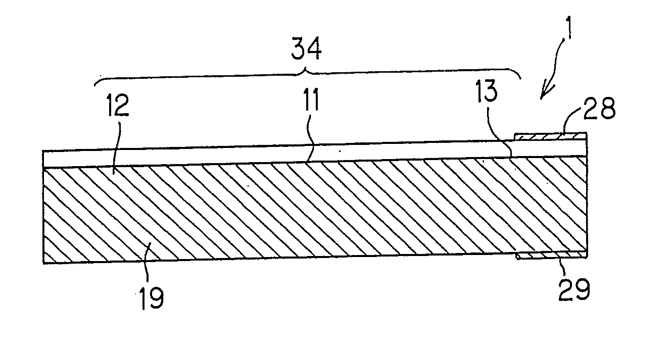
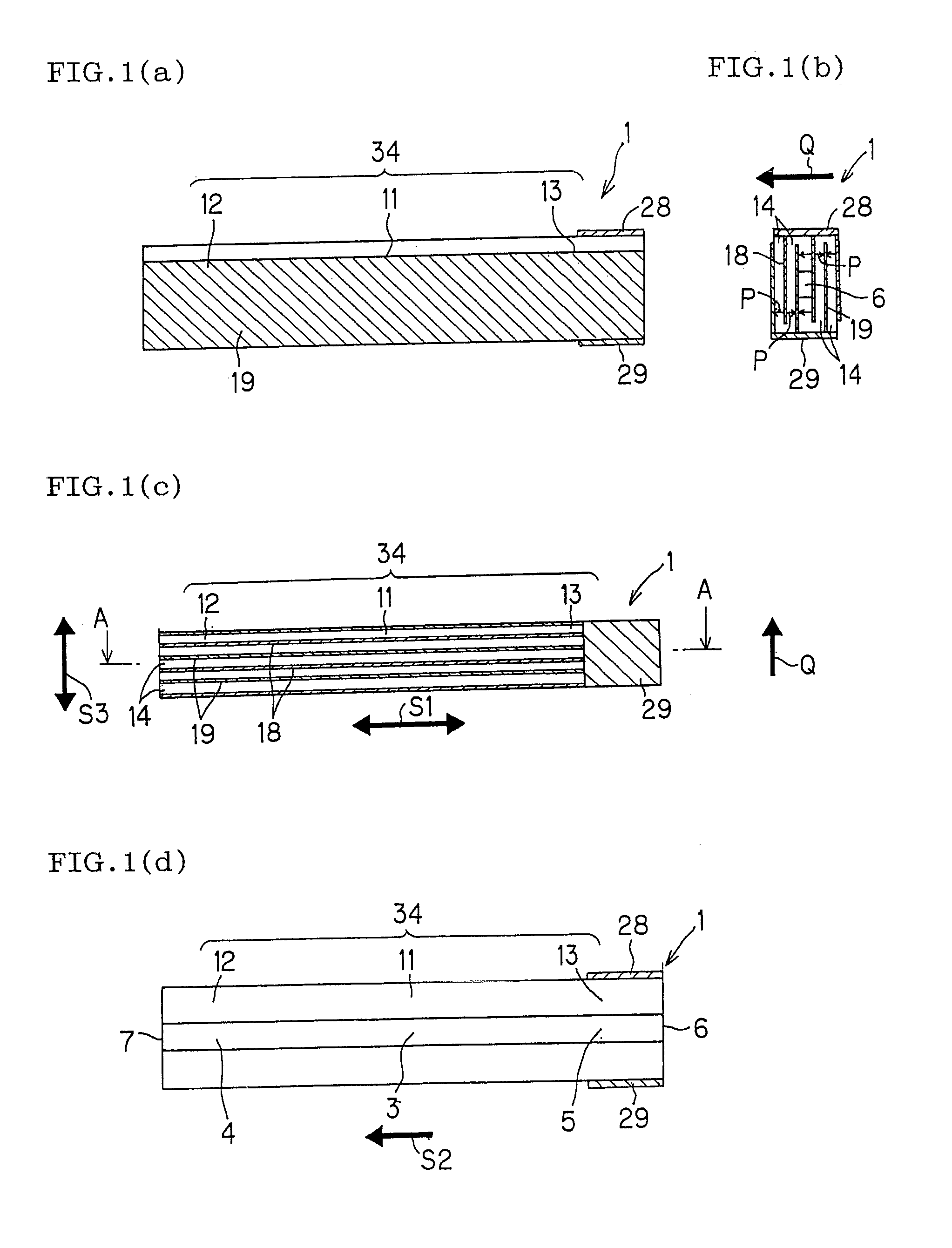
[0120] First, FIG. 1 is a diagram showing one embodiment of the liquid droplet discharging piezoelectric device according to the present invention, FIG. 1(a) is ...


PUM


Abstract

A liquid droplet discharging piezoelectric device 1 provided with a cavity member 11 with a built-in cavity 3; an introduction member 13 having introduction channel 5 connecting with the cavity 3; and a nozzle member 12 having nozzle channel 4 connecting with the cavity 3 on a side opposite to the channel 5. This liquid droplet discharging piezoelectric device 1 is provided with an introduction port 6, attached to the introduction member 13, capable of introducing a liquid into the cavity 3 via the introduction channel 5, and a discharge port 7, attached to the nozzle member 12, capable of discharging as droplets a liquid filled in the cavity 3 via the nozzle channel 40. Even in a case where an amount of liquid droplets is of a nanoliter (nl) order, excellent stability and reproducibility are attained, and the unit can stably be operated when attached to an apparatus.

Description

TECHNICAL FIELD [0001] The present invention relates to a liquid droplet discharge device having a structure in which a cavity (member) to be filled with a liquid is integrated with a nozzle (member) to discharge the liquid as droplets, the device being capable of easily treating micro liquid droplets of an nl order with good reproducibility. BACKGROUND ART [0002] In recent years, discharge means of micro liquid droplets is used as production means of products or the like in any field. The micro liquid droplet discharge means is used as, for example, ink discharge means in a printing apparatus; means for discharging and dispensing a predetermined liquid in a field of medical treatment, manufacturing organs of living body, drugs, food or the like; and means for forming an electrode film in a manufacturing process of a fuel cell or an electronic component. Especially in a blood analysis unit in the medical field, a genetic inspection unit or an inspection unit for new drug inspection ...

Claims


Application Information

Patent Timeline
IPC IPC(8): B41J2/045
CPCB41J2/14209B41J2002/14217B41J2202/11
Inventor OHNISHI, TAKAOYAMAMOTO, KAZUHIROISEKI, YOSHIHIROKIMURA, KOJIHIROTA, TOSHIKAZU
Owner NGK INSULATORS LTD
Why Eureka
Try Eureka