Compact zoom lens

a compact, zoom lens technology, applied in the field of zoom lenses, can solve the problems of difficult manual focus, inability to apply conventional zoom lenses to image projection devices, and inability to achieve the effect of compact structure, cost-effectiveness and high optical performan

Inactive Publication Date: 2007-05-31
ASIA OPTICAL INT LTD
View PDF5 Cites 26 Cited by
  • Summary
  • Abstract
  • Description
  • Claims
  • Application Information

AI Technical Summary

Benefits of technology

[0013] In comparison with the prior art, the present zoom lens has a compact structure and thus is cost-effective. A long back focal length for various aberration corrections is also secured by the present compact zoom lens. Both zooming and focusing are effected by the movement of the second, third and fourth lens groups. Various aberrations accompanying zooming can be effectively corrected so as to ensure high optical performance. When the present zoom lens is applied to an image projection device employing liquid crystal displays, a small-size, light-weight and low-cost projector can be obtained while ensuring a high-resolution and enhanced brightness projection image.

Problems solved by technology

However, such a conventional zoom lens cannot be applied to an image projection device due to its short back focal length.
A single lens usually has a small F-number, whereas a zoom lens usually has a large F-number, so the view appears dark and manual focusing becomes difficult.
Therefore, this conventional projection zoom lens is not fit for use in a compact projector because an optical system employing the four-group zoom lens, which has an overall focal length between 28 mm and 38 mm, will be bulky.
Further, The F-number of this conventional projection zoom lens, which is 1.7 to 2.0, may also not satisfy the requirement for a bright image in some cases.
However, this patent only roughly introduces the configuration and the function of the two-group movable lens, and does not provide any detailed description of conditions and parameters necessary to the design.
However, the increase in refractive power of the lens group will bring the problem of aberration fluctuations during zooming, and these aberration fluctuations are difficult to correct.
Accordingly, how to reduce the size and weight of the whole zoom lens system while maintaining high optical performance is a problem encountered by a zoom lens designer.

Method used


Image

  • Compact zoom lens
  • Compact zoom lens
  • Compact zoom lens

Examples


Embodiment Construction

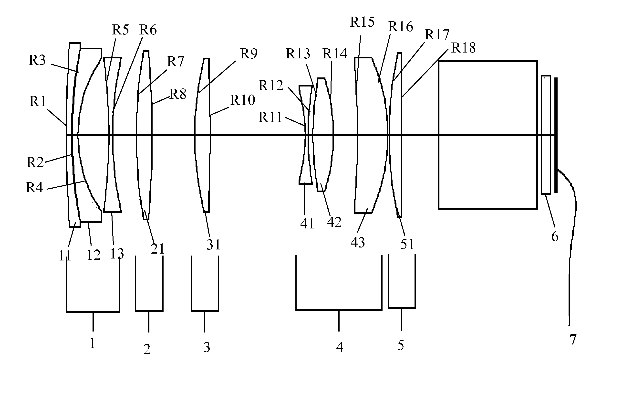
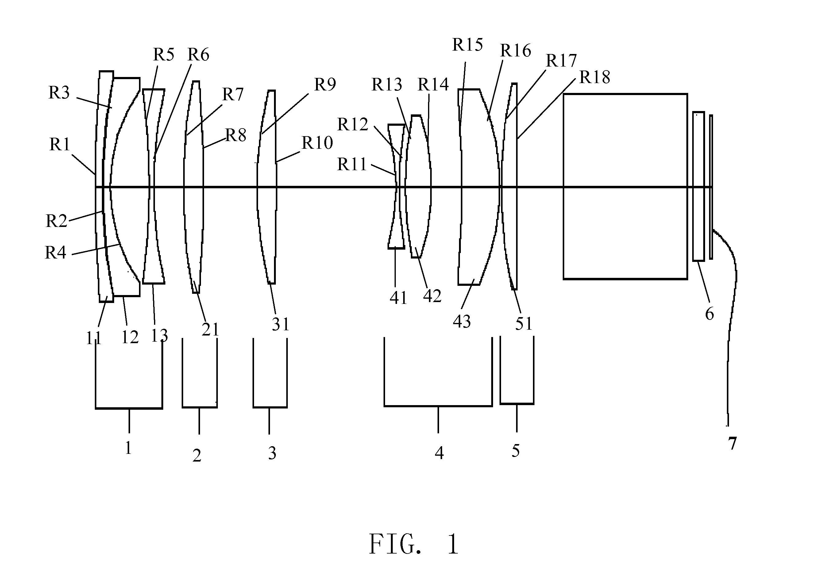
[0019]FIG. 1 shows the construction of a compact zoom lens in accordance with the concept of the present invention at the wide-angle end. The present compact zoom lens, which is positioned at the front of an optical device, may act as a projection zoom lens in an image projection device such as an LCD projector, or a zoom lens in an image pickup device such as a camera. Preferably, the present compact zoom lens is used in a high-resolution image projection device for projecting an image formed on an image-forming device (such as an LCD modulator) to a screen, and a high-resolution mobile projector in particular.

[0020] As shown in FIG. 1, the present compact zoom lens consists of, in order from an object side (a screen side for an image projection device, or an object side for an image pickup device) to an image side (the side of an image display member for an image projection device, or the side of an image forming member for an image pickup device), a first lens group 1 of negativ...


PUM


Abstract

A compact zoom lens includes, in order from an object side to an image side, a first lens group (1) of negative refractive power, and second, third, fourth and fifth lens groups (2, 3, 4, 5) of positive refractive power. The second, third and fourth lens groups are movable to effect zooming and focusing. During zooming from the telephoto end to the wide-angle end, the fourth lens group moves from the object side to the image side. The compact zoom lens has a long back focal length with various aberrations satisfactorily corrected, and a small F-number for enhanced image brightness.

Description

BACKGROUND OF THE INVENTION [0001] 1. Field of the Invention [0002] The present invention relates to a zoom lens, and particularly relates to a compact zoom lens for use in an image projection optical system of an image projection device and also for use in an image pickup optical system of an image pickup device. The present zoom lens offers a long back focal length and high-resolution combined with high image brightness with a compact package, and is particularly suitable for use in a mobile image projection device. [0003] 2. Description of Prior Art [0004] As an important element of an image projection optical system or an image pickup optical system, optical lenses are generally required to satisfy the high zoom ratio, high-resolution and high image quality requirements. A high zoom ratio lens generally consists of a plurality of lens groups and a considerable number of constituent lens elements, whereby the overall length of the lens is rather long. To meet the additional high-...

Claims


Application Information

Patent Timeline
Patent Type & Authority Applications(United States)
IPC IPC(8): G02B15/14
CPCG02B15/177G02B15/145531
Inventor KUO, CHUNG-YUAN
Owner ASIA OPTICAL INT LTD
Why Eureka
Try Eureka