Electrical signal-processing device integrating a flux sensor with a flux generator in a magnetic circuit

a technology of electric signal processing and flux generator, which is applied in the direction of pulse technique, instruments, record information storage, etc., can solve the problems of large devices and relatively cumbersome, and achieve the effect of minimizing transformer action and minimizing transformer action

Active Publication Date: 2007-05-31
WESTERN DIGITAL TECH INC
View PDF41 Cites 62 Cited by
  • Summary
  • Abstract
  • Description
  • Claims
  • Application Information

AI Technical Summary

Benefits of technology

[0033]FIG. 16 is a side cross-sectional view of another embodiment of the present invention with three input coils arranged on the legs of a magnetic circuit having two inner loops and an outer loop that minimizes transformer action between the coils when two time-varying input signals are applied thereto;
[0034]FIG. 17 is ...

Problems solved by technology

Such devices are rather large and relatively cumbersome because suc...

Method used


Image

  • Electrical signal-processing device integrating a flux sensor with a flux generator in a magnetic circuit
  • Electrical signal-processing device integrating a flux sensor with a flux generator in a magnetic circuit
  • Electrical signal-processing device integrating a flux sensor with a flux generator in a magnetic circuit

Examples


embodiment 100

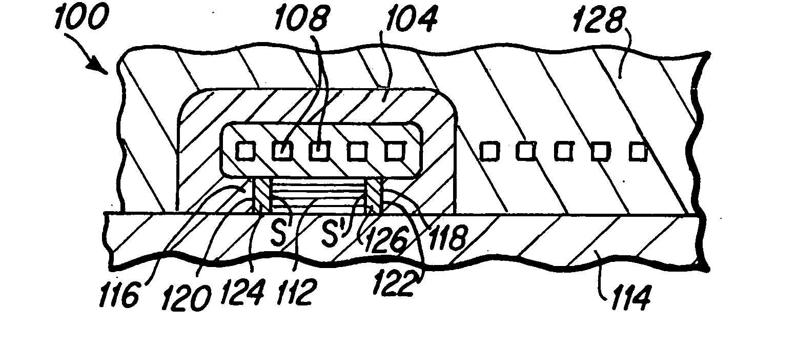
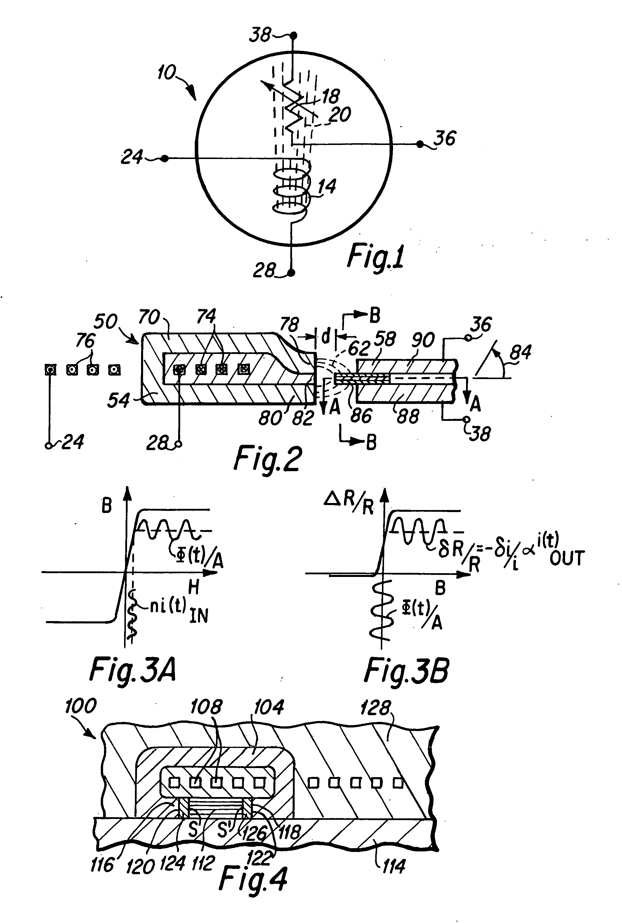
[0068]FIG. 4 is a side cross-sectional view that depicts another embodiment 100 of a transfluxistor in which the sensor is directly embedded in a gap of the flux generator. As depicted therein, a yoke 104 comprising thin film planar layers, surrounds inside portions of the thin film conductive induction lines connected to form coil turns 108 of a flux generating coil in a thin film planar layer, where a thin film planar sensor element 112 is fabricated upon a substrate 114 between thin film planar pole tip portions 116 and 118 of the yoke 104. The pole tips 116 and 118 have end surfaces 120 and 122 respectively that are generally perpendicular to the planar sensor layers of the thin film planar layers of the magnetic sensor 112. In this embodiment 100, the sensor 112 is separated from the end surfaces 120 and 122 of the pole tips 116 and 118 by electrically insulating thin film planar portions of the gap, g1 124 and g2 126. Such electrically insulating gap portions are non-magnetic,...

embodiment 1900

[0120]FIG. 19A depicts in cross-section along line DD of FIG. 19B an embodiment 1900 of the present invention that uses helical coils to facilitate tighter packing of sensors within the magnetic circuit of a transfluxistor. As depicted in FIG. 19A, a first MR sensor 1930 is disposed between first pole tip portions 1920 and 1924 of a yoke 1904. Also depicted in FIG. 19A is a second MR sensor 1930 disposed between second pole tip portions 1954 and 1958 of the yoke 1904. Electrically insulating portions of the gap 1944 and 1940 are interposed between first sensor sides and end surfaces of the first pole tips; and similarly, electrically insulating portions of the gap 1964 and 1960 are interposed between second sensor sides and end surfaces of the second pole tips, to prevent the shunting of sensor current away from the sensor. The sensor 1930, pole tip portions 1920, 1924, 1954, and 1958 of the yoke 1904, and electrically insulating portions of the gap 1940, 1944, 1960, and 1964 are fa...


PUM


Abstract

An electrical signal processing device includes at least one thin film flux generator and at least one thin film magnetic sensor. Each flux generator includes at least one conductive induction line that is connected to at least one lead of a pair of input leads, and a yoke that surrounds the conductive induction line. The yoke has at least one pair of pole tips, and a gap is disposed between the end surfaces of each pair of pole tips. A magnetic sensor is disposed in the gap, and a pair of output leads is connected to the sensor. An alternative embodiment may include two or more conductive induction lines that are connected to respective separate pairs of input leads. Alternatively, two or more conductive induction lines may connect to one another to form an induction coil. The flux generator and magnetic sensor are preferably formed on a single substrate to create an integrated device.

Description

BACKGROUND OF THE INVENTION [0001] 1. Field of the Invention [0002] The present invention relates generally to electrical signal processing devices, and more particularly to a device incorporating a magnetic circuit having high flux transfer efficiency between one or more magnetic flux generators, and one or more magnetic flux sensors. [0003] 2. Description of the Prior Art [0004] Magnetic circuit devices that include a flux generator and a flux sensor are known in the art. Typically the flux generator and the flux sensor are fabricated separately and assembled proximate each other, such that the sensor is placed within the magnetic field created by the flux generator. Such devices are rather large and relatively cumbersome because such prior art devices have purposes other than electrical signal processing. There is therefore a need for devices that are small in scale and in which the flux generator and magnetic sensor are fabricated proximate each other incorporating a magnetic ci...

Claims


Application Information

Patent Timeline
IPC IPC(8): G11B5/33
CPCG01R33/04G01R33/091G11C11/16H01L27/22H03K17/82H03K19/166H10B61/00H10N59/00
Inventor PARKER, MICHAEL ANDREW
Owner WESTERN DIGITAL TECH INC
Why Eureka
Try Eureka