Monolithic capacitor and mounting structure thereof

a monolithic capacitor and mounting structure technology, applied in the direction of fixed capacitors, stacked capacitors, fixed capacitor details, etc., can solve the problems of high-frequency characteristics degradation and steep impedance characteristics, and achieve the effect of low esl

Active Publication Date: 2007-05-31
MURATA MFG CO LTD
View PDF27 Cites 35 Cited by
  • Summary
  • Abstract
  • Description
  • Claims
  • Application Information

AI Technical Summary

Benefits of technology

[0008] To overcome the problems described above, preferred embodiments of the present invention provide a monolithic capacitor in which ESL is decreased and ESR is increased at the same time, and a mounting structure of the monolithic capacitor which enables the low ESL characteristics of the monolithic capacitor in which ESL is decreased to be sufficiently exhibited.

Problems solved by technology

Therefore, the problem of steep impedance characteristics arises.
This causes the problem of degradation of high-frequency characteristics.

Method used


Image

  • Monolithic capacitor and mounting structure thereof
  • Monolithic capacitor and mounting structure thereof
  • Monolithic capacitor and mounting structure thereof

Examples


Embodiment Construction

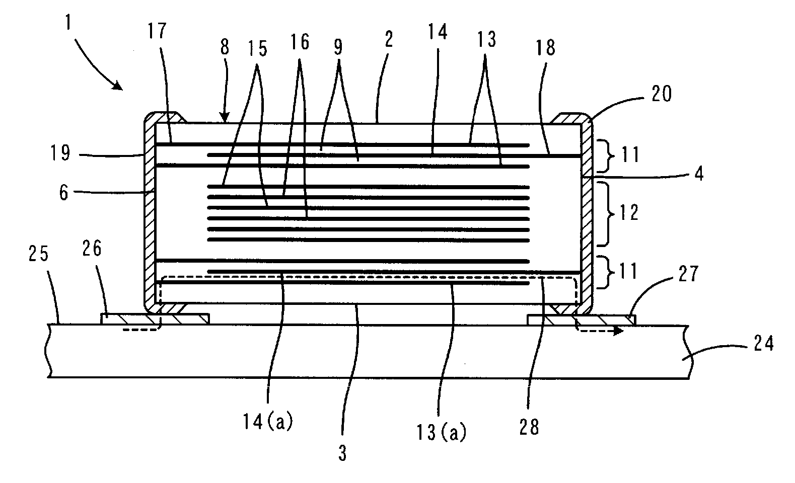
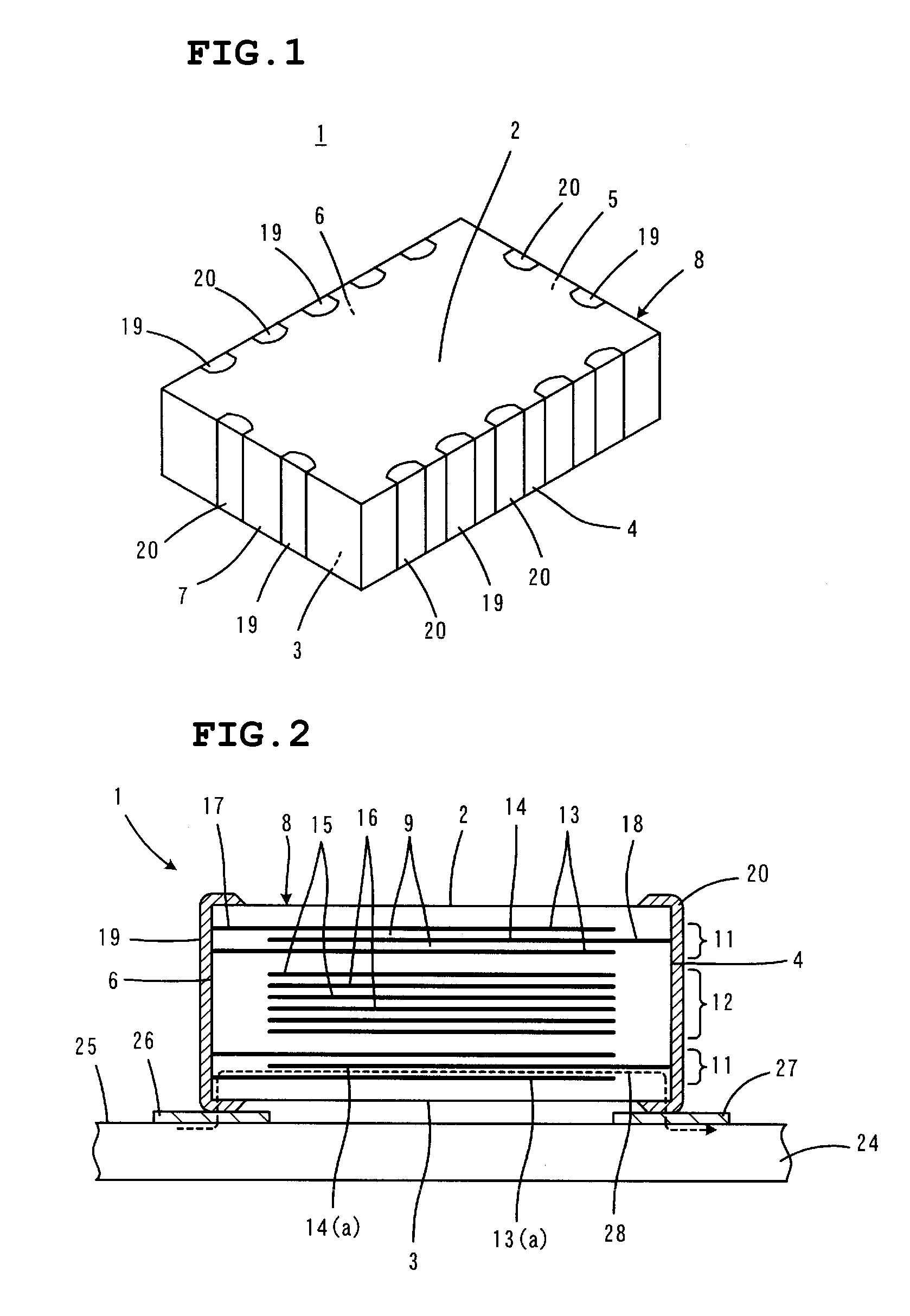
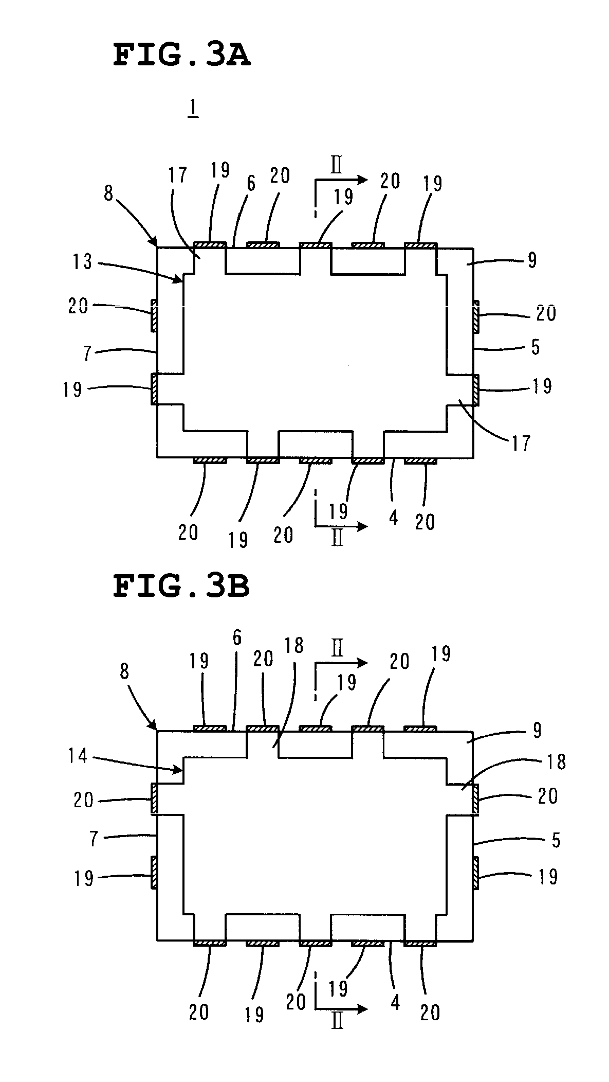
[0065] FIGS. 1 to 4B show a monolithic capacitor according to a first preferred embodiment of the present invention. FIG. 1 is a perspective view showing the appearance of the monolithic capacitor 1, and FIG. 2 is a sectional view showing a mounting structure of the monolithic capacitor 1. In FIG. 2, the monolithic capacitor 1 is shown in cross-section taken along lines II-II in FIGS. 3A, 3B, 4A and 4B described later.

[0066] The monolithic capacitor 1 preferably includes a substantially rectangular main capacitor unit 8 having two opposing principal surfaces 2 and 3 and four side surfaces 4, 5, 6, and 7 connecting the principal surfaces 2 and 3. The main capacitor unit 8 has a monolithic structure including a lamination of a plurality of dielectric layers 9 parallel to the principal surfaces 2 and 3, and composed of, for example, a dielectric ceramic material.

[0067] As shown in FIG. 2, the main capacitor unit 8 includes first capacitor portions 11 and a second capacitor portion 12...


PUM

PropertyMeasurementUnit
capacitanceaaaaaaaaaa
thicknessaaaaaaaaaa
thicknessaaaaaaaaaa

Abstract

A monolithic capacitor includes a main capacitor unit having first capacitor portions and a second capacitor portion arranged in a direction of lamination, with the first capacitor portion located towards at least one end in the direction of lamination, so that the first capacitor portion is located closer to a mounting surface than the second capacitor portion. The number of pairs of third and fourth lead-out portions for third and fourth internal electrodes in the second capacitor portion is less than the number of pairs of first and second lead-out portions for first and second internal electrodes in the first capacitor portion, so that the first capacitor portion contributes to decreasing ESL while the second capacitor portion contributes to increasing ESR.

Description

BACKGROUND OF THE INVENTION [0001] 1. Field of the Invention [0002] The present invention relates to monolithic capacitors and mounting structures of the monolithic capacitors. More specifically, the present invention relates to a monolithic capacitor that is used in a high-frequency circuit and to a mounting structure of the monolithic capacitor. [0003] 2. Description of the Related Art [0004] As a decoupling capacitor that is used in a power supply circuit for an MPU (Micro Processing Unit) in a high frequency range on the order of several GHz, for example, a monolithic capacitor having a structure described in Japanese Unexamined Patent Application Publication No. 11-144996 (Patent Document 1) is known. In the monolithic capacitor, a plurality of terminals is provided such that adjacent terminals have opposite polarities. Thus, the length of paths of currents from positive terminals to negative terminals is relatively short, and currents flow in various ways. Furthermore, current...

Claims


Application Information

Patent Timeline
Patent Type & Authority Applications(United States)
IPC IPC(8): H01G4/06
CPCH01G4/30H01G4/385H01G4/12H01G4/38
Inventor TAKASHIMA, HIROKAZUUEOKA, HIROSHITAKAGI, YOSHIKAZU
Owner MURATA MFG CO LTD
Why Eureka
Try Eureka