Power converters

a technology of power converters and converters, which is applied in the direction of motors, ac-dc conversion, wind energy generation, etc., can solve the problems of loss of control loss of ability to control reactive current essential for voltage support functions demanded by network codes, loss of dc link voltage control and the ability to control reactive current during voltage dip

Active Publication Date: 2007-05-31
GE POWER CONVERSION
View PDF7 Cites 172 Cited by
  • Summary
  • Abstract
  • Description
  • Claims
  • Application Information

AI Technical Summary

Benefits of technology

[0034] The second controller can modify an error signal arising from the difference between the voltage demand signal indicative of the level of voltage to be achieved at the network terminals of the filter and the voltage feedback signal measured at the network terminals of the filter in accordance with a signal derived from the direct axis current demand signal. The purpose of modifying the error signal in accordance with a signal derived from the direct axis current demand signal is that a characteristic can be realised which can contribute to current sharing between multiple generators which are connected to a particular supply network.
[0037] Each individual power converter preferably includes a step-up transformer electrically connected between the associated filter and the parallel connection. The arrangement may also include a step-up transformer electrically connected between the parallel connection and the supply network. The top-level voltage feedback signal can be measured at either the supply network side or the parallel connection side of the step-up transformer electrically connected between the parallel connection and the supply network. The advantage of measuring the top-level voltage feedback signal on the supply network side of the step-up transformer is that the measurement on the parallel connection side is subject to regulation across the step-up transformer. This regulation effect is therefore eliminated if the measurement is made on the supply network side.

Problems solved by technology

In this arrangement, a loss of network voltage during a supply dip leads to loss of control of the dc link voltage.
Consequently, the ability to control the reactive current that is essential for voltage support functions demanded by the network codes is also lost.
Both schemes therefore suffer from the disadvantage that during the situation where the network voltage is lost, then the dc link voltage control and the ability to control reactive current during the voltage dip are also lost.

Method used


Image

  • Power converters
  • Power converters
  • Power converters

Examples


Embodiment Construction

Power Converter Topology

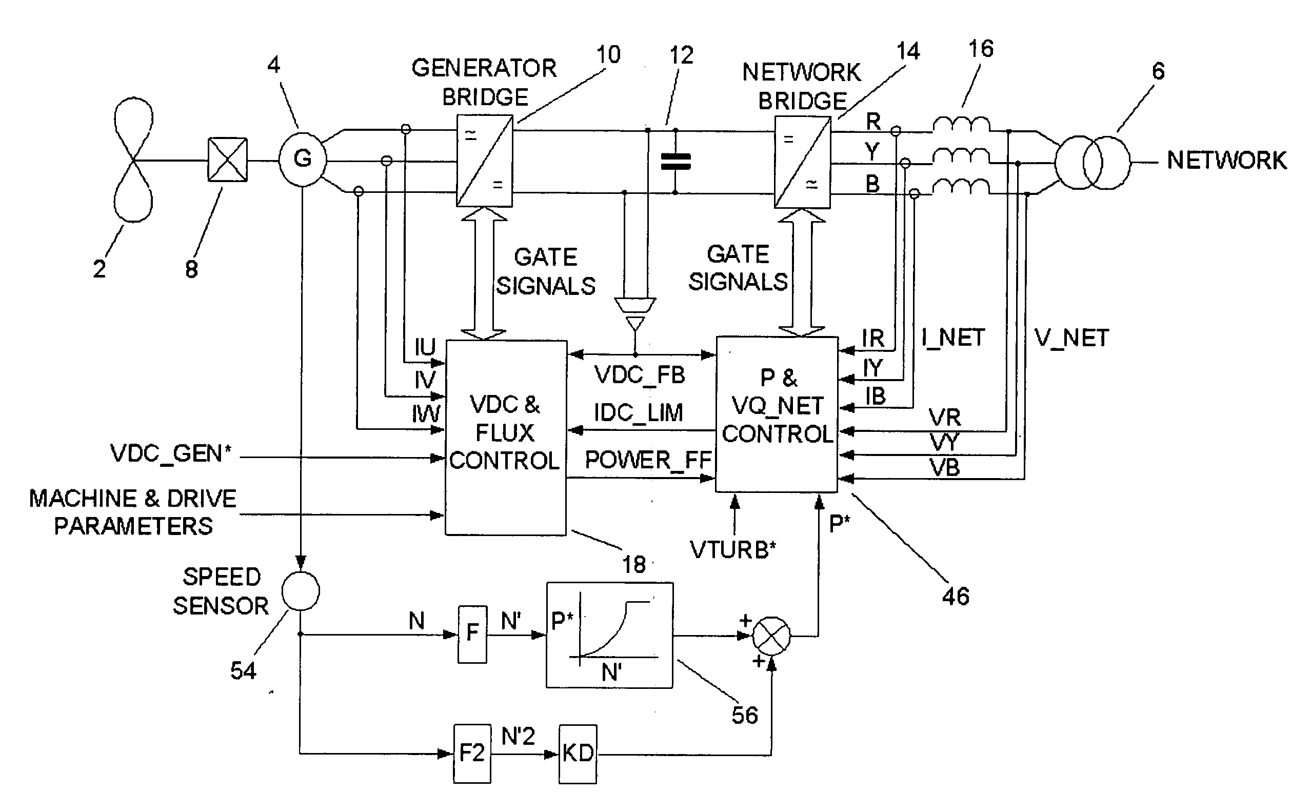
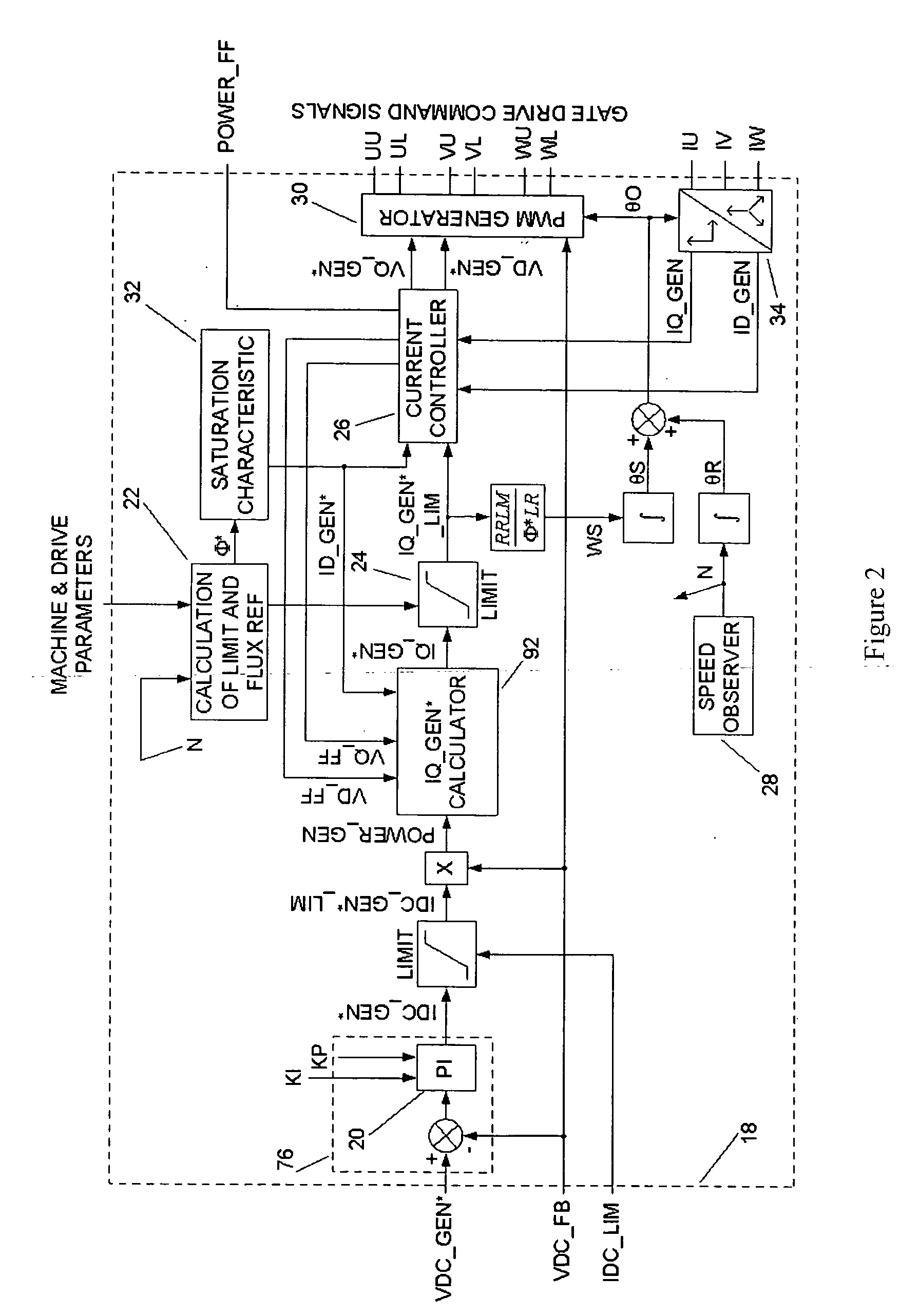
[0098] The basic topology of the power converter will be outlined with reference to FIG. 1.

[0099] The power converter is used to interface between a wind turbine 2 driving a variable speed ac induction generator 4 and a nominally fixed frequency power network (labelled NETWORK). The wind turbine typically includes three turbine blades (one turbine blade or two turbine blades or more than three turbine blades are also possible) mounted on a rotating shaft and whose pitch can be controlled by means of a pitch actuator in order to optimise and / or limit the capture of wind energy into the generator 4. A gearbox 8 is used to connect the rotating shaft to the rotor of the variable speed generator 4. In some cases, the rotating shaft can be connected directly to the rotor of the variable speed generator. This means that the speed of rotation of the rotor varies as a function of the wind speed and that the frequency of the voltage developed at the stator of the ge...


PUM


Abstract

The present invention provides_a power converter that can be used to interface a generator (4) that provides variable voltage at variable frequency to a supply network operating at nominally fixed voltage and nominally fixed frequency and including features that allow the power converter to remain connected to the supply network and retain control during supply network fault and transient conditions. The power converter includes a generator bridge (10) electrically connected to the stator of the generator (4) and a network bridge (14). A dc link (12) is connected between the generator bridge (10) and the network bridge (14). A filter (16) having network terminals is connected between the network bridge (14) and the supply network. A first controller (18) is provided for controlling the operation of the semiconductor power switching devices of the generator bridge (14). Similarly, a second controller (46) is provided for controlling the operation of the semiconductor power switching devices of the network bridge (14). The first controller (18) uses a dc link voltage demand signal (VDC13 GEN*) indicative of a desired dc link voltage to control the semiconductor power switching devices of the network bridge (10) to achieve the desired level of dc link voltage that corresponds to the dc link voltage demand signal (VDC13 GEN*). The second controller (46) uses a power demand signal (P*) indicative of the level of power to be transferred from the dc link to the supply network through the network bridge (14), and a voltage demand signal (VTURB*) indicative of the voltage to be achieved at the network terminals of the filter (16) to control the semiconductor power switching devices of the network bridge (14) to achieve the desired levels of power and voltage that correspond to the power and voltage demand signals (P* and VTURB*).

Description

CROSS REFERENCE TO RELATED APPLICATION [0001] This application claims the benefit of United Kingdom Patent Application No. 0523087.5, filed Nov. 11, 2005, U.S. Patent Provisional Application Ser. No. 60 / 736,205, filed Nov. 14, 2005 which was converted to U.S. patent application Ser. No. 11 / 292,669, filed Dec. 2, 2005. FIELD OF THE INVENTION [0002] The present invention relates to power converters, and in particular to power converters that can be used to interface generators providing variable voltage at variable frequency to a power grid or supply network at nominally fixed voltage and frequency. The present invention also includes features that allow the power converters to remain connected to the supply network and retain control during network fault and transient conditions. The power converters are particularly suitable for use with, but not restricted to, generators that are driven by wind turbines. BACKGROUND OF THE INVENTION [0003] It is possible to convert wind energy to el...

Claims


Application Information

Patent Timeline
Patent Type & Authority Applications(United States)
IPC IPC(8): H02M1/14
CPCH02M5/4585H02P9/102H02P2101/15Y02E10/763H02J3/382H02J3/386H02J2300/28H02J2300/20H02J3/381Y02E10/76
Inventor JONES, RODNEYBROGAN, PAUL BRIANGRONDAHL, ERIKSTIESDAL, HENRIK
Owner GE POWER CONVERSION
Why Eureka
Try Eureka