
Method of operating a radio communications network, terminal and base station

Inactive Publication Date: 2007-05-31
ALCATEL LUCENT SAS
View PDF20 Cites 6 Cited by
  • Summary
  • Abstract
  • Description
  • Claims
  • Application Information

AI Technical Summary

Benefits of technology

[0011] Therefore, it is an object of the present invention to provide an improved method of operating a radio communications network with better service availability and reliability as compared to prior art solutions.
[0015] Thus, particularly if the terminal is a mobile terminal, employing the inventive method reduces the probability of an interruption of any service based on said data transmission to the terminal or the data delivery to a terminal's user from the cache memory, respectively. The terminal or its user advantageously experiences a seamless service despite intermittent connectivity.
[0016] According to an advanced embodiment of the present invention, data which is transmitted in advance to said terminal is transmitted with the highest data rate possible for said data transmission. Thereby, the time required for filling the cache memory of the terminal is minimized, and furthermore, the probability of experiencing a radio coverage discontinuity during filling said cache memory is also reduced.
[0018] Yet another very advantageous embodiment of the present invention proposes that no data is transmitted from said base station to said terminal if a maximum possible data rate is below a predetermined threshold. This ensures that data transmissions with extremely low data rates are avoided, which would be very inefficient because of usual protocol overheads and the like.
[0020] According to yet another advantageous embodiment of the present invention, a data transmission from said base station to said terminal is performed depending on a filling status of said cache memory of said terminal, which inter alia enables to interrupt a data transmission or to reduce the data rate, respectively, if the cache memory of the terminal is full. On the other hand, according to this variant of the inventive method, it is also possible to increase a data rate used for the data transmission to the terminal if the cache memory of the terminal is not sufficiently filled. It is also possible to enforce a data transmission at a very low data rate to avoid starving of the terminal or its cache memory, respectively.
[0026] The classification may e.g. be used to control the data rates chosen for data transmissions between the base station and the terminal in a very simple manner.

Problems solved by technology

Methods and systems of the above mentioned type are known from prior art and suffer from disadvantages such as discontinuities in a radio coverage which enables said radio link between the base station and the terminal.
Such discontinuities may e.g. cause interruptions of a data transmission between the base station and the terminal and are thus highly undesired.
If the real time traffic is not limited in such situations, the data transmission to the terminal, which may in particular be a non-real time data transmission, is affected or even interrupted.
These solutions have a complexity cost and their efficiency has not yet been proved in real deployment cases.
A second approach to tackle the problem of radio coverage discontinuities is based on a densification of the radio deployment, which is not favourable since it increases network costs.
Yet another approach, which is based on call admission control (CAC) mechanisms, disadvantageously limits the number of possible users of a corresponding radio communications network.
However, solutions based on scalable codecs do not guarantee seamless services, because if there are poor radio transmission conditions, in particular the quality of video data so transmitted is heavily degraded, and in the worst case, only voice data will be transmitted.

Method used


Image

  • Method of operating a radio communications network, terminal and base station
  • Method of operating a radio communications network, terminal and base station
  • Method of operating a radio communications network, terminal and base station

Examples


Embodiment Construction

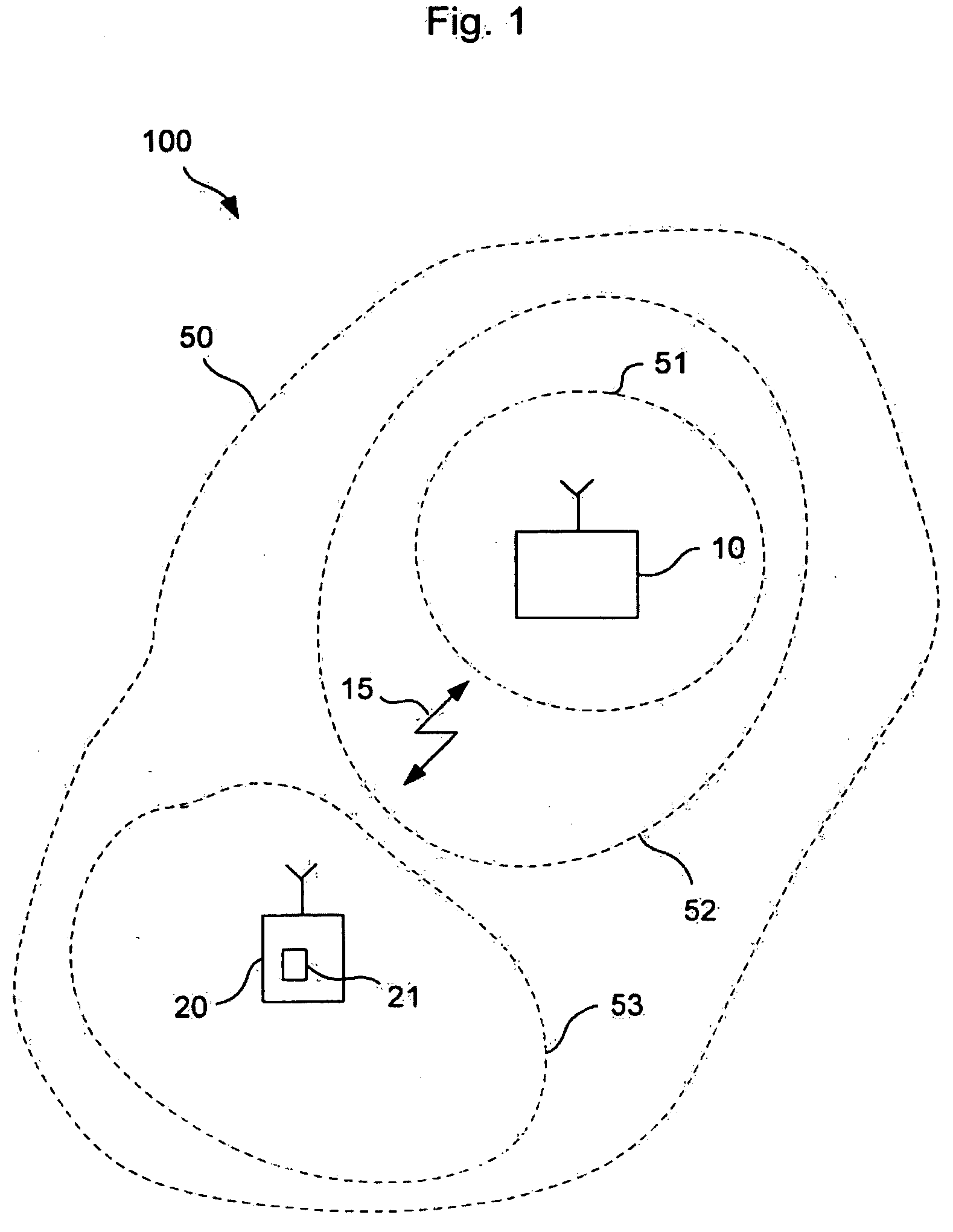
[0034]FIG. 1 depicts a radio communications network 100 which comprises a base station 10 and a mobile terminal 20 that is capable of exchanging data via a radio link 15 between the base station 10 and the terminal 20.

[0035]FIG. 1 also depicts a radio coverage area 50 of the base station 10. Said radio coverage area 50 is classified into various areas 51, 52, 53 each of which is characterized by specific data transmission conditions such as a maximum data transmission rate or a carrier to interference ratio.

[0036] For instance, area 51 which is next to the base station 10, is characterized by a comparatively high data transmission rate which is due to the proximity of a area 51 to the base station 10.

[0037] In contrast thereto, area 52 does not support such a high data transmission rate as is given within area 51. The next area, area 53, which currently comprises the mobile terminal 20, is characterized by the lowest possible data transmission rate within the whole radio coverage...


PUM


Abstract

The invention relates to a method of operating a radio communications network (100), wherein data is transmitted from a base station (10) of said network (100) to a terminal (20) via a radio link (15). The inventive method is characterized in that data to be transmitted from said base station (20) to said terminal (20) is transmitted in advance to said terminal depending on current data transmission conditions of said radio link (15) and stored to a cache memory (21) of said terminal (20).

Description

[0001] The invention is based on a priority application EP05292528.6 which is hereby incorporated by reference. TECHNICAL FIELD [0002] The invention relates to a method of operating a radio communications network, wherein data is transmitted from a base station of said network to a terminal via a radio link. [0003] The invention further relates to a terminal capable of receiving data from a base station of a radio communications network via a radio link, as well as to a base station. BACKGROUND OF THE INVENTION [0004] Methods and systems of the above mentioned type are known from prior art and suffer from disadvantages such as discontinuities in a radio coverage which enables said radio link between the base station and the terminal. Such discontinuities may e.g. cause interruptions of a data transmission between the base station and the terminal and are thus highly undesired. [0005] In particular, voice services and other real time services require an increased part of available ra...

Claims


Application Information

Patent Timeline
IPC IPC(8): H04Q7/00H04N7/24H04W28/14H04W28/26
CPCH04L47/10H04L47/14H04L47/2416H04L47/25H04L49/90H04N21/23406H04N21/238H04N21/23805H04N21/262H04N21/41407H04N21/4331H04N21/44004H04N21/44209H04N21/4424H04N21/6377H04N21/658H04N21/6582H04W28/14H04W28/26H04W28/0205H04W28/0231H04W28/0278H04W8/04
Inventor ROUFFET, DENISFAYE, JEAN-CLAUDECAPDEVIELLE, VERONIQUE
Owner ALCATEL LUCENT SAS
Learn More