System and method for discovering the locations of potential layer-2 nodes in a telecommunications network

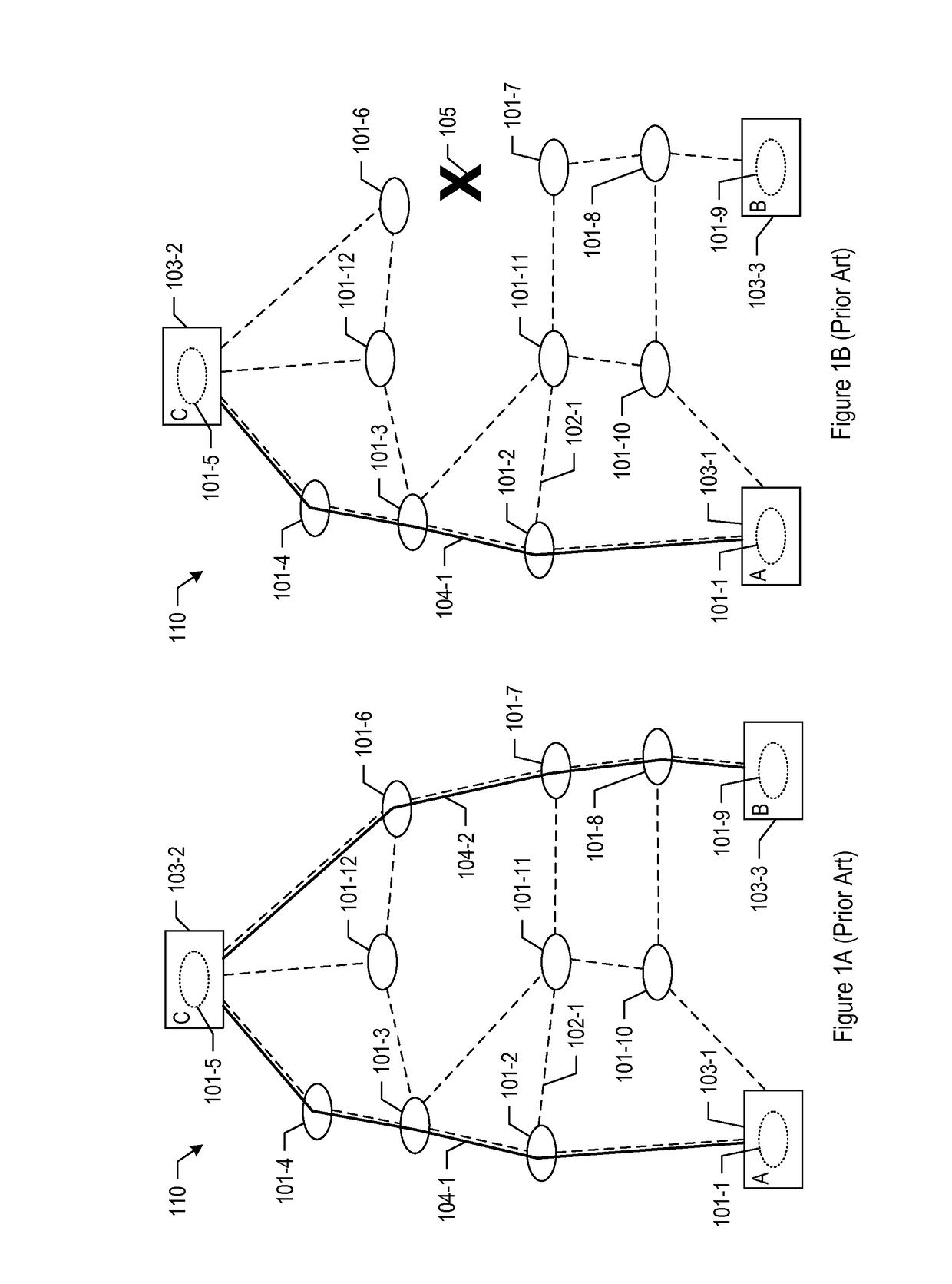
a technology of telecommunications network and location, applied in the field of telecommunications, can solve problems such as the disruption of data packet routing performed in the telecommunications system b>100/b>, and achieve the effect of increasing the availability of one or more services and improving service availability

Active Publication Date: 2017-03-30
TATA COMM AMERICA
View PDF6 Cites 0 Cited by
  • Summary
  • Abstract
  • Description
  • Claims
  • Application Information

AI Technical Summary

Benefits of technology

[0010]The invention enables the discovery and identification of locations at which to deploy new Layer-2 nodes within a telecommunications network, without at least some of the disadvantages in the prior art. The disclosed technique is intended to identify Layer-2 nodes at locations where they can improve service availability when deployed, especially in geographic regions that suffer frequent or simultaneous cable breaks, or both. In accordance with the illustrative embodiment of the present disclosure, the locations of the new Layer-2 nodes depend on the underlying Layer-0 network topology, as well as on the existing Layer-2 topology. Thus, the disclosed technique features a cross-layer approach—that is, across Layer-2 and Layer-0—that takes these factors into account and evaluates the locations in a way that can considerably increase the availability of one or more services offered in the telecommunications network.

Problems solved by technology

There are situations in which the data packet routing performed within telecommunications system 100 can be disrupted.
Depending on various factors, such disruptions can be frequent, and multiple disruptions can occur simultaneously with one another.

Method used


Image

  • System and method for discovering the locations of potential layer-2 nodes in a telecommunications network
  • System and method for discovering the locations of potential layer-2 nodes in a telecommunications network
  • System and method for discovering the locations of potential layer-2 nodes in a telecommunications network

Examples


Embodiment Construction

[0029]Layer 0—For the purposes of this specification and the claims, “layer 0” is defined as the transmission medium or media in data communication network.

[0030]Layer 2—For the purposes of this specification and the claims, “layer 2” is defined as the Data Link layer of the Open Systems Interconnection (OSI) communication model.

[0031]Route segment—For the purposes of this specification and the claims, “route segment” is defined as the transmission medium path between two layer-0 nodes, with no other layer-0 nodes in between.

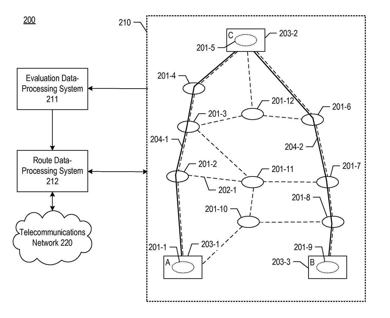
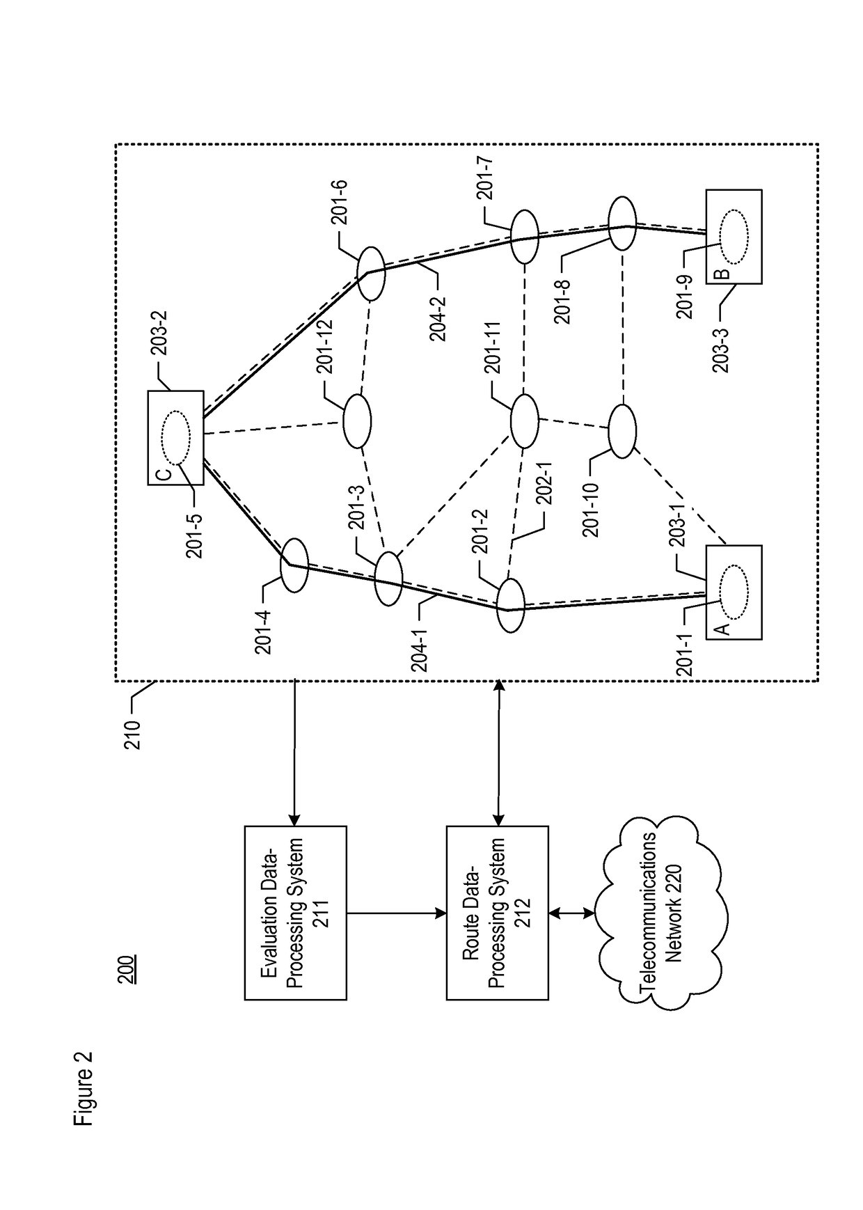
[0032]Network topology—For the purposes of this specification and the claims, “network topology” is defined as the arrangement of various elements (e.g., nodes, links, etc.) of a computer network or other telecommunications network. It may be depicted physically or logically.

[0033]Bundle—For the purposes of this specification and the claims, “bundle” is defined as the layer-2 connectivity between two layer-2 nodes, with no other layer-2 nodes in between.

[0034]La...


PUM


Abstract

A technique for discovering and identifying locations at which to deploy new Layer-2 nodes within a telecommunications network. The disclosed technique is intended to identify Layer-2 nodes at locations where they can improve service availability when deployed, especially in geographic regions that suffer frequent or simultaneous cable breaks, or both. The locations of the new Layer-2 nodes depend on the underlying Layer-0 network topology, as well as on the existing Layer-2 topology. Thus, the disclosed technique features a cross-layer approach that takes these factors into account and evaluates the locations in a way that can considerably increase the availability of one or more services offered in the telecommunications network.

Description

FIELD OF THE INVENTION[0001]moon The present invention relates to telecommunications in general, and, more particularly, to discovering the locations of potential layer-2 nodes to be deployed for use in a telecommunications network.BACKGROUND OF THE INVENTION[0002]FIG. 1A depicts a schematic diagram of a portion of a telecommunications system in the prior art. The depicted portion includes telecommunications network 110, which comprises: layer-0 nodes 101-1 through 101-12, layer-0 route segments 102-1 through 102-17, layer-2 nodes 103-1 through 103-3, and layer-2 bundle 104-1 through 104-2. The elements within telecommunications network 110 are interrelated as shown.[0003]Network 110 enables devices such as user endpoints to exchange data packets with one another. In particular, network 110 constitutes a wide-area network (WAN), although it could alternatively constitute a local-area network (LAN) or other type of network. Network 110 operates on Layer-2 (L-2) Provider Backbone Brid...

Claims


Application Information

Patent Timeline
Patent Type & Authority Applications(United States)
IPC IPC(8): H04L12/707H04W64/00H04L12/751H04W16/18H04L12/721H04L45/24H04L45/02
CPCH04L45/22H04W16/18H04W64/003H04L45/02H04L45/66H04L41/12
Inventor KHALIL, AHMAD NAJIBNURUJJAMAN, MOHAMMADUDDIN, MOHAMMAD FAISAL
Owner TATA COMM AMERICA
Why Eureka
Try Eureka