Water-lifting pump apparatus and method for controlling operation thereof

a pump and water pump technology, applied in the direction of machines/engines, liquid fuel engines, positive displacement liquid engines, etc., can solve the problems of affecting damage to components, and high cost of electric motors as actuators, so as to achieve easy control of the flow rate of water falling into the suction tank

Inactive Publication Date: 2007-05-31
EBARA CORP
View PDF5 Cites 15 Cited by
  • Summary
  • Abstract
  • Description
  • Claims
  • Application Information

AI Technical Summary

Benefits of technology

[0035] In this manner, with the waterfall passes mainly through the bypass piping,

Problems solved by technology

If internal combustion engines are reversed in the absence of any countermeasures, then they will be damaged by the. reversing torque.
However, using the electric motor as the actuator is more costly for the reason of general economic efficiency than using the internal combustion engine as the actuator because the electric motor needs a separate non-utility power

Method used


Image

  • Water-lifting pump apparatus and method for controlling operation thereof
  • Water-lifting pump apparatus and method for controlling operation thereof
  • Water-lifting pump apparatus and method for controlling operation thereof

Examples


Embodiment Construction

[0061] Embodiments of the present invention will be described in detail below with reference to the drawings.

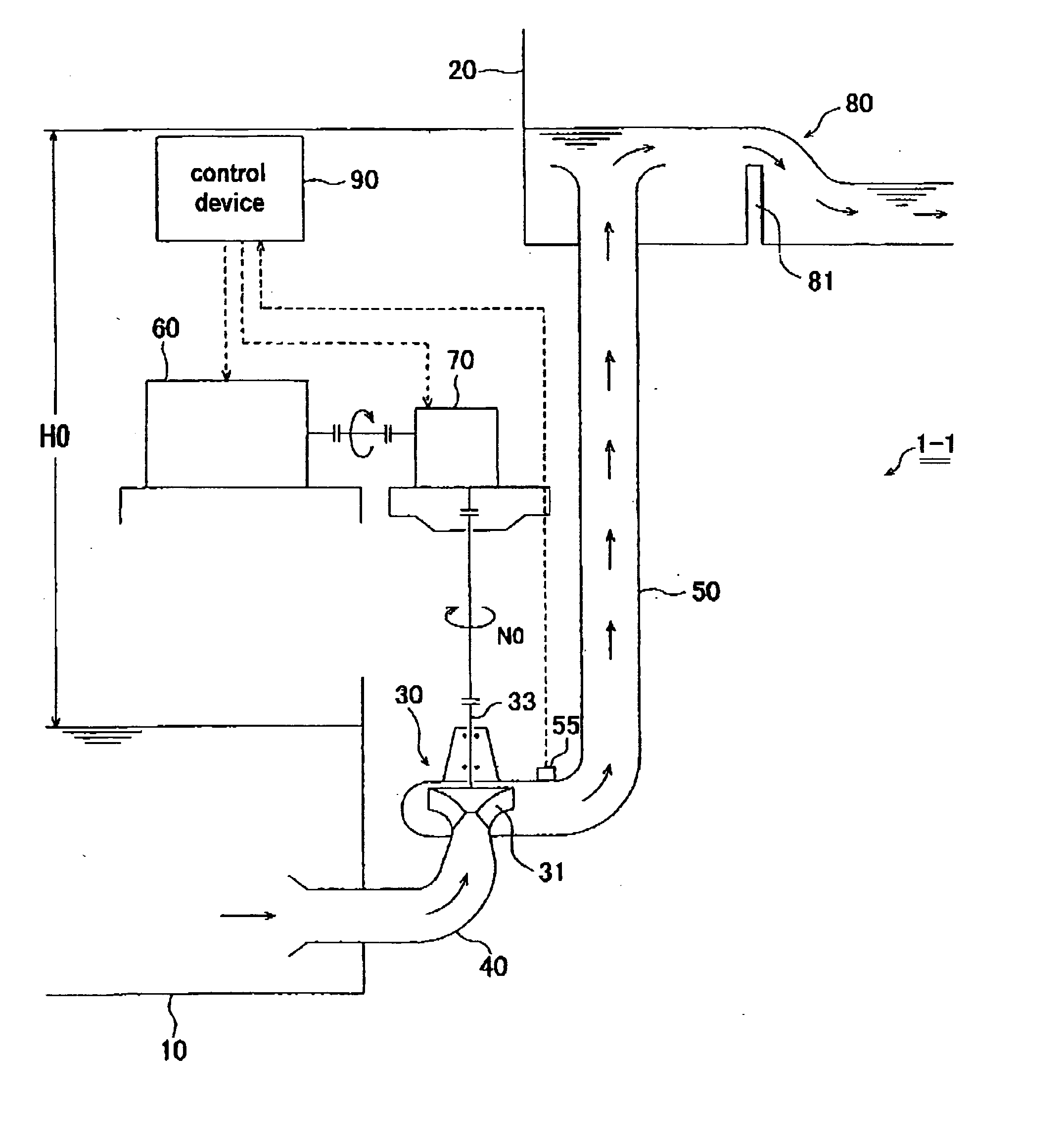
[0062]FIG. 3 is an overall schematic view of a water-lifting pump apparatus 1-1 according to an embodiment of the present invention.

[0063] The water-lifting pump apparatus 1-1 shown in FIG. 3 is a water-lifting pump apparatus for use in a deep subterranean water discharge pump station, for example, and has a suction tank 10 for collecting rainwater or the like, a discharge tank 20 installed in a position higher than the suction tank 10, and a pump 30 for pumping water in the suction tank 10 into the discharge tank 20. The water-lifting pump apparatus 1-1 also has an suction piping 40 interconnecting the suction side of the pump 30 and the suction tank 10, a discharge piping 50 interconnecting the discharge side of the pump 30 and the discharge tank 20, an actuating means 60 for driving the pump 30, a transmission (speed reducer) 70 connected between the actuating means 60 a...


PUM


Abstract

There are provided a water-lifting pump apparatus which is free of a discharge valve and a check valve, is low in cost, and is capable of reducing vibration and noise due to a waterfall after the end of water pumping operation, and a method of controlling operation of the water-lifting pump apparatus. The water-lifting pump apparatus has a suction tank (10), a discharge tank (20), a pump (30) for pumping water in the suction tank (10) into the discharge tank (20), and a discharge piping (50) connected to a discharge side of the pump, an actuating means (60) for actuating the pump (50), a reverse flow preventing mechanism (80) for preventing a reverse flow of water pumped into the discharge tank (20) toward the discharge piping (50), and a back flow rate control means (90) for controlling the flow rate of a waterfall falling from the discharge piping (50) into the suction tank (10) when pumping operation is finished.

Description

TECHNICAL FIELD [0001] The present invention relates to a water-lifting pump apparatus suitable for use in a rainwater discharge pump station or the like and a method of controlling operation of the water-lifting pump apparatus. BACKGROUND ART [0002] As more and more efforts have been made in recent years for utilizing deep underground regions in urban areas, there have been trends towards rainwater discharge pump stations also installed in deep subterranean regions. A typical water-lifting pump apparatus for use in such rainwater discharge pump stations has a discharge valve and a check valve that are connected to a discharge side of the pump. FIG. 1 is a schematic view showing a conventional water-lifting pump apparatus for use in a deep subterranean discharge pump station. As shown in FIG. 1, the conventional water-lifting pump apparatus is of a general structure which includes a pump 300 having an suction piping 301 connected to a suction tank 310 and a discharge piping 303 conn...

Claims


Application Information

Patent Timeline
IPC IPC(8): F04B49/06F04D9/00F04D13/16F04D15/00F04D29/66
CPCF04D9/007F04D13/16F04D15/0022F04D15/0066F04D29/669
Inventor KAMATA, ISAMUSUZUKI, SHINJIKANNO, HIDEKIENOMOTO, TAKASHIKURAMASU, MASAHIRO
Owner EBARA CORP
Why Eureka
Try Eureka