
Liquid chemical supply system having a plurality of pressure detectors

a technology of liquid chemical supply system and detector, which is applied in the direction of positive displacement liquid engine, pump control, piston pump, etc., to achieve the effect of reducing the size and cost of the present system and simplifying the construction

Active Publication Date: 2007-05-31
OCTEC INC +1
View PDF7 Cites 25 Cited by
  • Summary
  • Abstract
  • Description
  • Claims
  • Application Information

AI Technical Summary

Benefits of technology

[0006] An object of the present invention is primarily to provide a liquid chemical supply system that can always perform suitable pressure feedback control even when the pressure setting value of the operation pressure differs due to a change in the type of liquid chemical, etc., thereby controlling the discharge flow rate of a liquid chemical with high precision.

Problems solved by technology

For example, when a low viscosity liquid chemical is to be used, the pressure setting value will have to be lowered, and thus this type of problem can occur.

Method used


Image

  • Liquid chemical supply system having a plurality of pressure detectors
  • Liquid chemical supply system having a plurality of pressure detectors
  • Liquid chemical supply system having a plurality of pressure detectors

Examples


Embodiment Construction

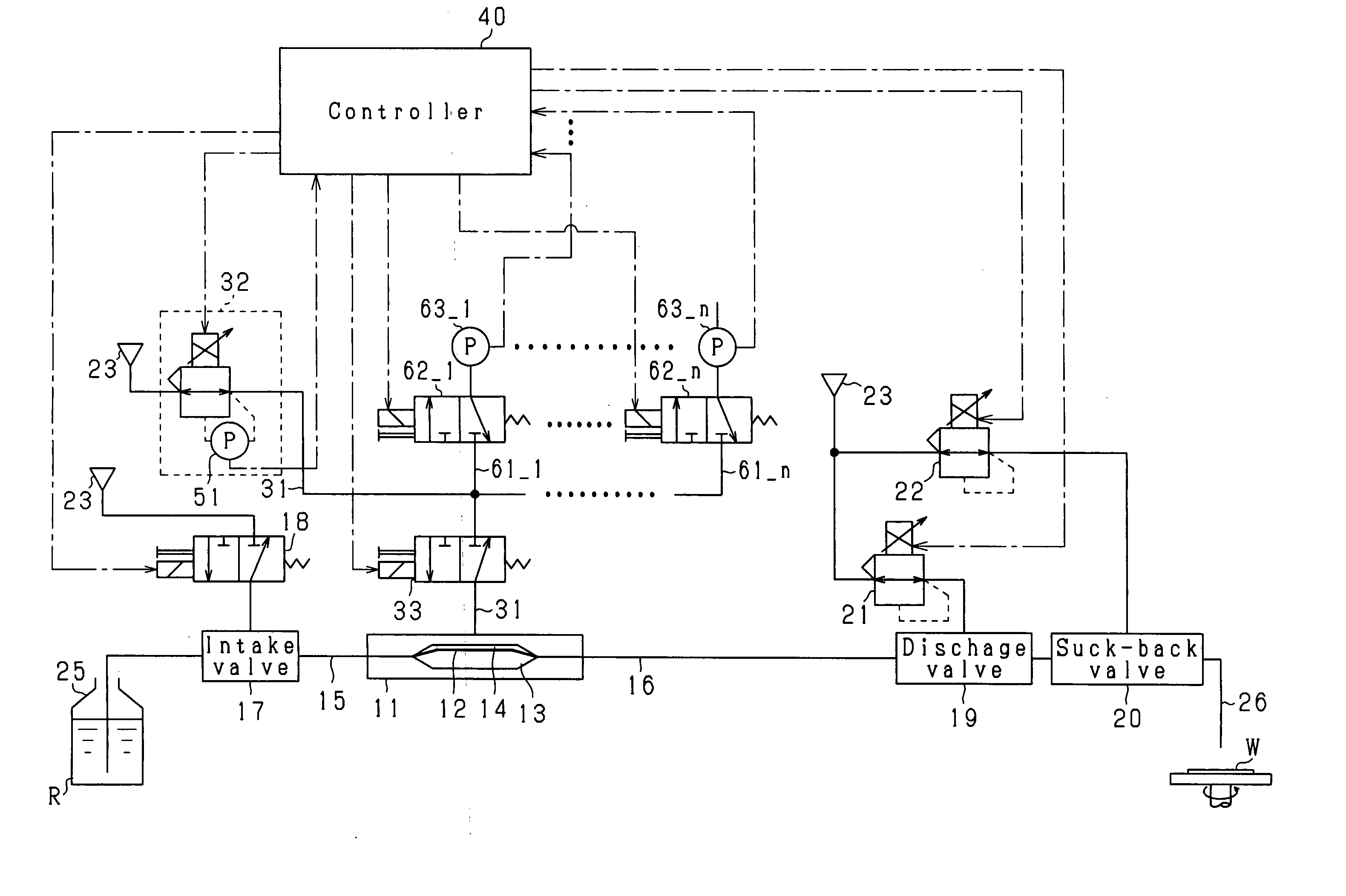
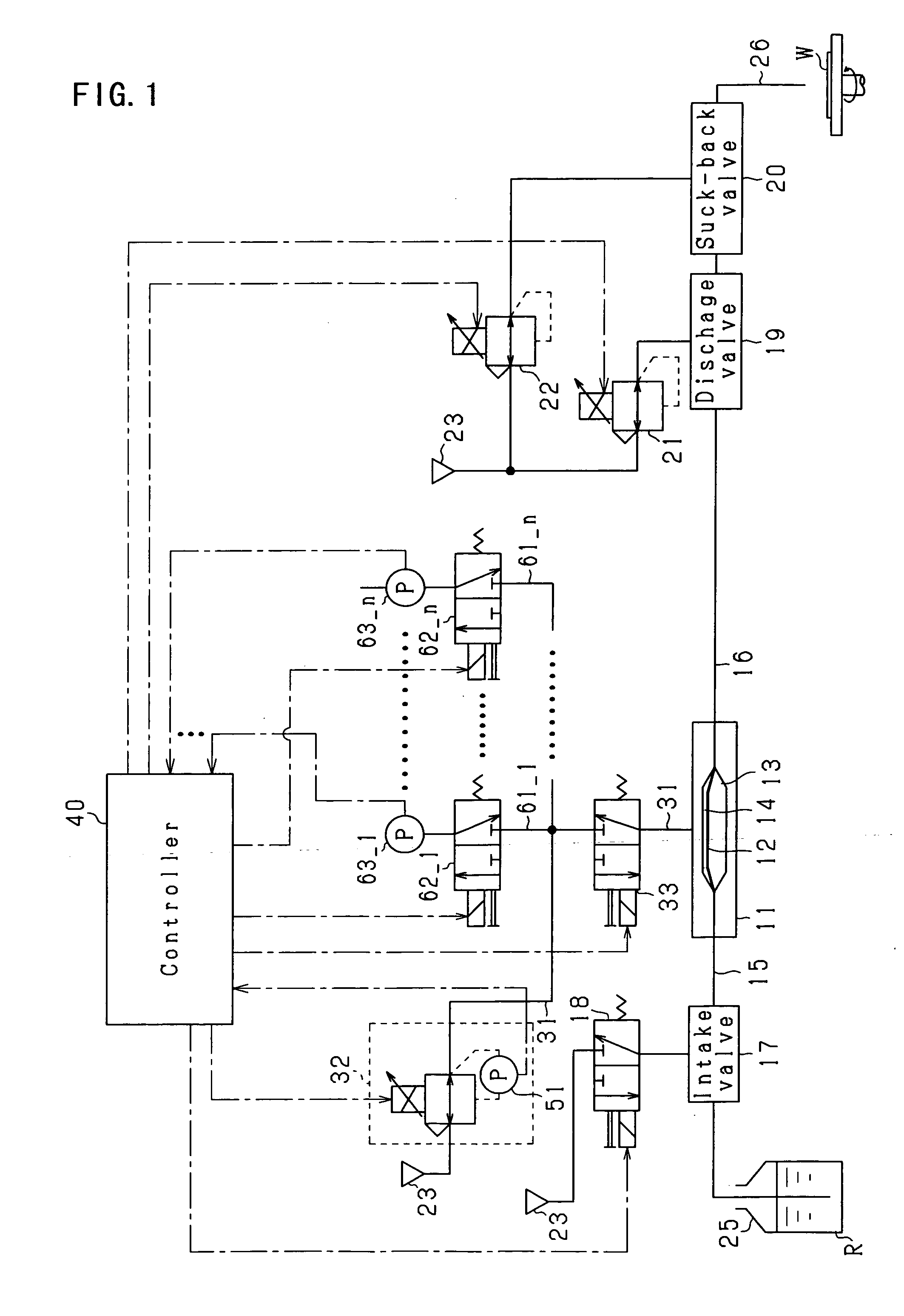
[0022] An embodiment of the present invention will be described below in accordance with the drawings. An overview of the liquid,chemical supply system according to the present embodiment will be described based upon FIG. 1.

[0023] A liquid chemical supply pump (hereinafter simply referred to as a pump) 11 is provided in the liquid chemical supply system of FIG. 1 in order to draw in and discharge liquid chemical. The pump 11 has a pump chamber 13 and an operation chamber 14 that are separated by a diaphragm 12 comprising a flexible membrane, and an intake pathway 15 (comprising an intake tube or the like) and a discharge pathway 16 (comprising a discharge tube or the like) are connected to the pump chamber 13. An intake valve 17 that is an intake side on-off valve is provided along the intake pathway 15, and the intake valve 17 opens and closes in response to the electrical conduction state of a solenoid valve 18. In addition, a discharge valve 19 that is a discharge side on-off val...


PUM


Abstract

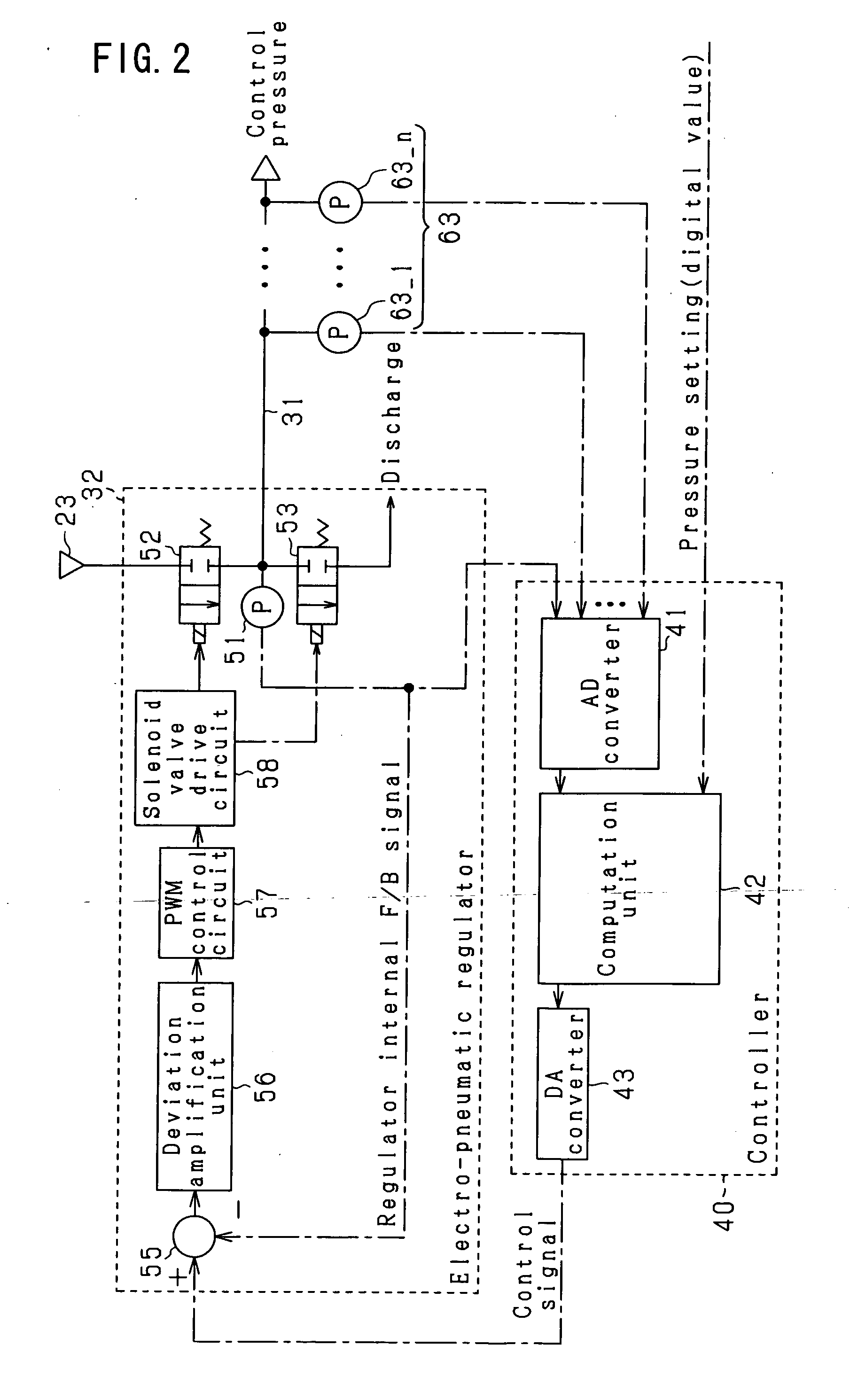
[Problem] To always perform accurate pressure feedback control, and control the discharge flow rate of liquid chemical with high precision, even in situations in which the pressure setting value of the operation pressure differs due to changes in the type of liquid chemical, etc. [Means of solution] A pump 11 has a pump chamber 13 and an operation chamber 14 separated by a diaphragm 12 comprised of a flexible membrane, and performs the intake and discharge of liquid chemical in accordance with the change in pressure inside the operation chamber 14. An electro-pneumatic regulator 32 supplies operation air to the operation chamber 14. In addition, in the present system, a plurality of pressure sensors 51, 63 having different pressure detection ranges is provided as pressure detection means for detecting the operation air pressure. A controller 40 selectively employs any of the detection results of the plurality of sensors 51, 63 in accordance with the pressure setting value of the operation air that is set for each use, and performs pressure feedback control.

Description

[0001] The present application claims priority based on Japan Patent Application No. 2005-301439, filed on Oct. 17, 2005, and the entire contents of that application are incorporated by reference in this specification. FIELD OF THE INVENTION [0002] The present invention relates to a liquid chemical supply system that, among other things, serves to intake a liquid chemical by means of a liquid chemical pump, and then discharge a fixed quantity thereof, and also relates to a liquid chemical supply system that is ideal for use in a liquid chemical usage process of a semiconductor manufacturing device, such as a liquid chemical application process. BACKGROUND ART [0003] A liquid chemical pump is employed in a liquid chemical usage process of a semiconductor manufacturing device in order to apply a predetermined quantity of liquid chemical to a semiconductor wafer. One liquid chemical pump that is known has a pump chamber filled with liquid chemical, and an operation chamber that introdu...

Claims


Application Information

Patent Timeline
Patent Type & Authority Applications(United States)
IPC IPC(8): F04B49/00
CPCF04B49/08H01L21/02
Inventor OKUMURA, KATSUYATOYODA, TETSUYAITO, TOMOHIROMURAKUMO, AKIRASAKAI, ATSUYUKI
Owner OCTEC INC
Learn More