
Barrier and battery module having the same

a battery module and barrier technology, applied in the field of barriers and battery modules having barriers, can solve the problems of battery module malfunction, abnormal high, and difficulty in adjusting the structure of the barrier

Inactive Publication Date: 2007-05-31
SAMSUNG SDI CO LTD
View PDF5 Cites 32 Cited by
  • Summary
  • Abstract
  • Description
  • Claims
  • Application Information

AI Technical Summary

Benefits of technology

[0015] Aspects of the present invention provide a barrier and a battery module having the barrier, by which a welding failure between a pair of panels may be prevented.
[0016] Aspects of the present invention also provide a barrier and a battery module having the barrier, by which constructability of the battery module may be improved by accurately interposing the barrier between the unit batteries.
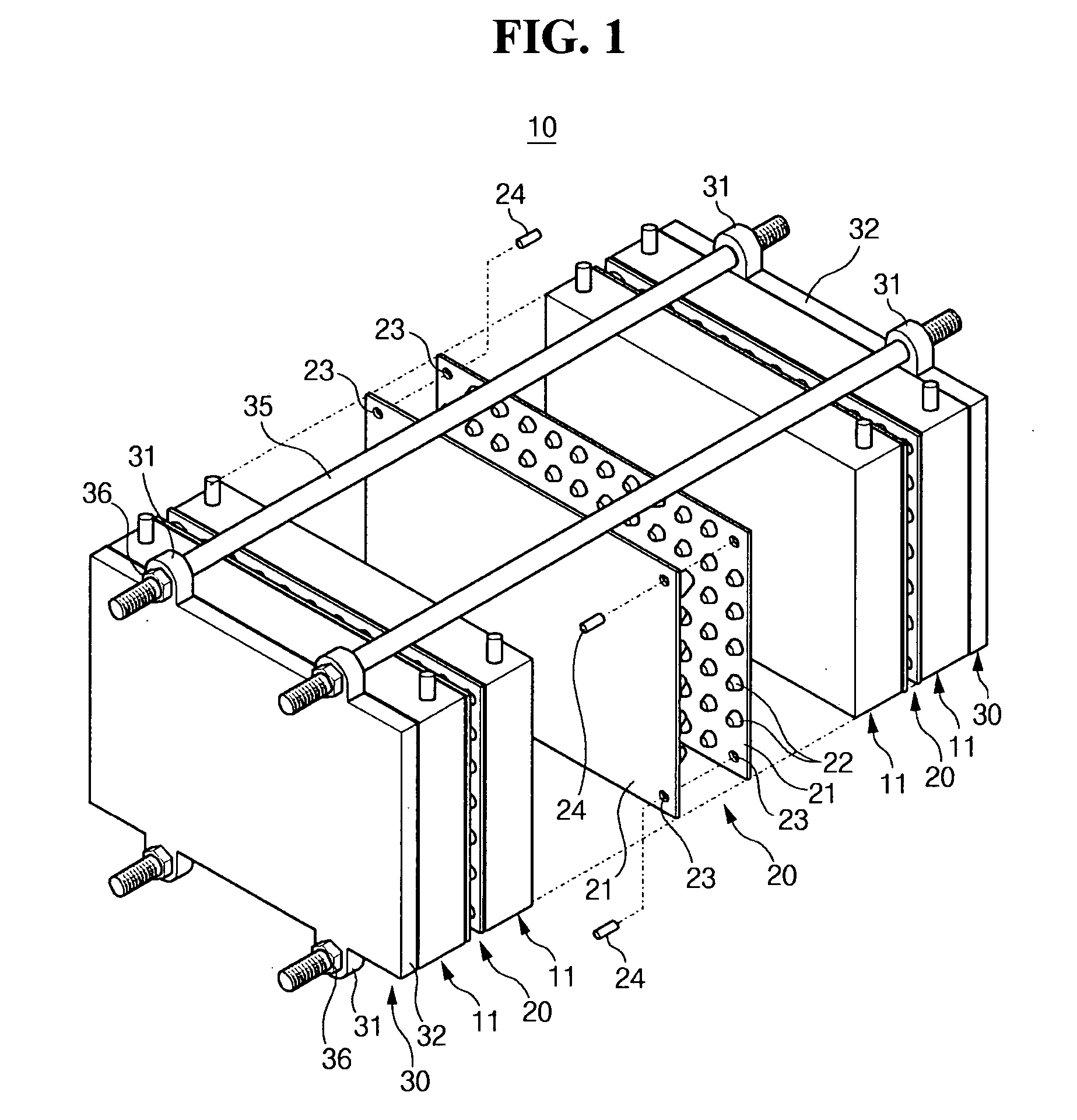
[0022] A length of the locking pin may be larger than a thickness of the barrier, so that a portion of the locking pin is protruded from an outer surface of the barrier. The unit battery may have a recess on an outer surface in a position corresponding to the locking pin, so that a leading end of the locking pin is inserted into the recess. As a result, positions of the unit battery and the barrier can be accurately adjusted just by inserting the leading end of the locking pin protruded from an outer surface of the barrier into the recess formed in an outer surface of the casing of the unit battery.

Problems solved by technology

When the heat is not appropriately sunken, the heat generated from each unit battery may cause an abnormally high temperature in the battery module, and may eventually cause the battery module to malfunction.
The aforementioned barrier structure may have some problems, however, with a bonding failure during a process of bonding the pair of panels to provide a single barrier.
This bonding failure is generated because appropriately adjusting positions of the pair of panels is difficult.
Accordingly, a welding failure between the pair of panels may occur as the positions of the protrusions of the panels deviate from one another.
As a result of the structural failure in the barrier, the cooling medium may be inappropriately circulated, a heat sink characteristic of the battery module may be degraded, the structural integrity of the barrier may be degraded, and the battery lifetime may also be reduced.
In addition, since accurately adjusting positions between the barrier and the unit battery in a conventional battery structure is difficult, an assembling failure may also occur.

Method used


Image

  • Barrier and battery module having the same
  • Barrier and battery module having the same
  • Barrier and battery module having the same

Examples


second embodiment

[0053] According to an embodiment of the present embodiment, an inner space of the protrusions is filled with a material that is substantially similar to that of the panel 21 as shown in FIG. 4. On the contrary, according to the present invention, the inner space of the protrusions 22′ can be vacant as shown in FIG. 5. As a result, the pairs of the panels 21 may be readily combined and their positions may be adjusted as needed by simply bonding both panels using the locking pins 24.

[0054] Although not shown in the drawings, the shape of the protrusions 22 may be hemispherical, cylindrical, or cubic in addition to that the shapes described for the protrusions that are discussed above. Alternatively, the shape of the protrusions 22 may be a polygonal cone such as a circular cone, a triangular cone, and a rectangular cone. Similarly, although not shown in the drawings, the shapes of the jointing holes 23 and the locking pins 24 are not limited those shown in the drawings, and may be a ...

third embodiment

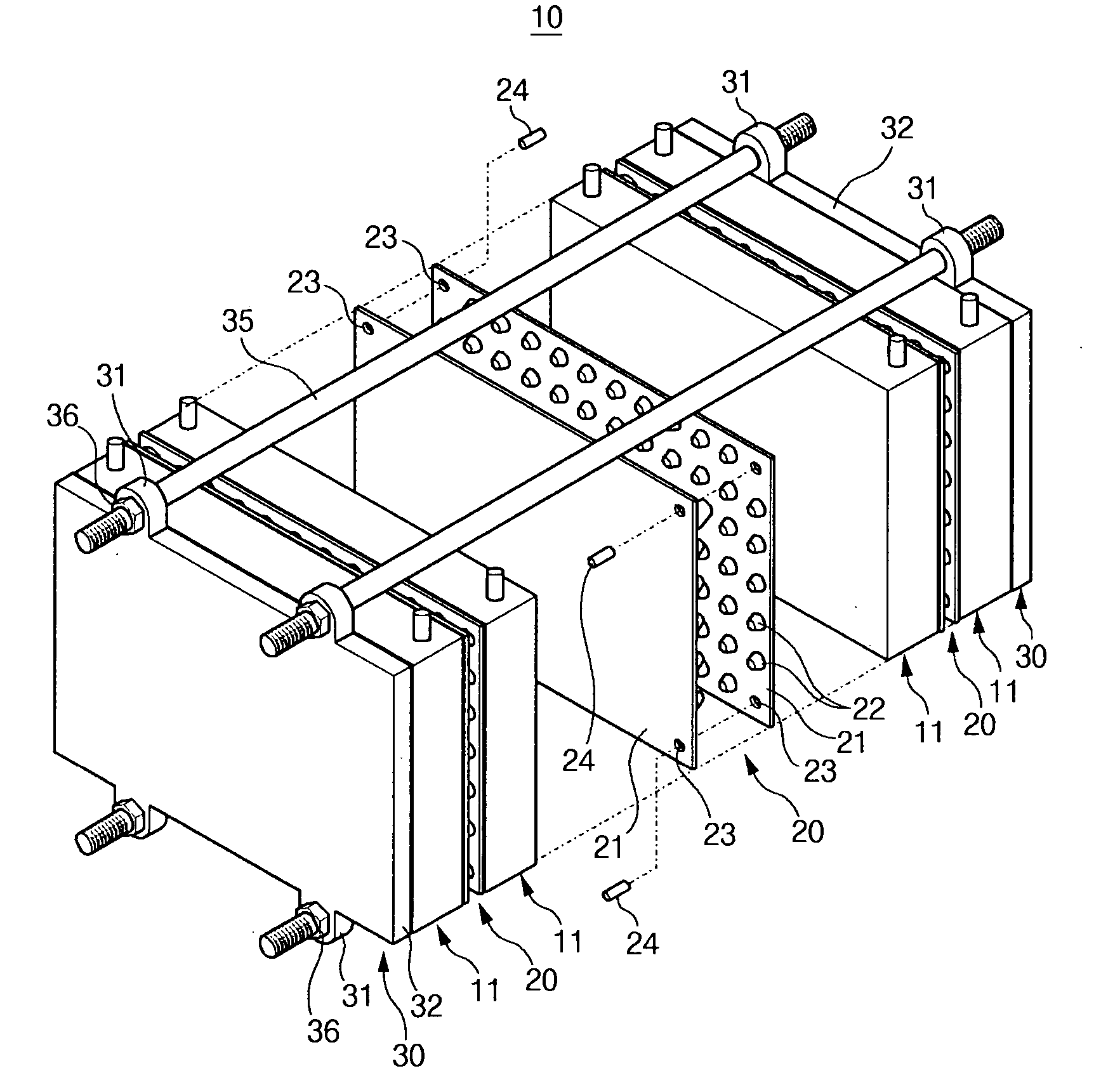
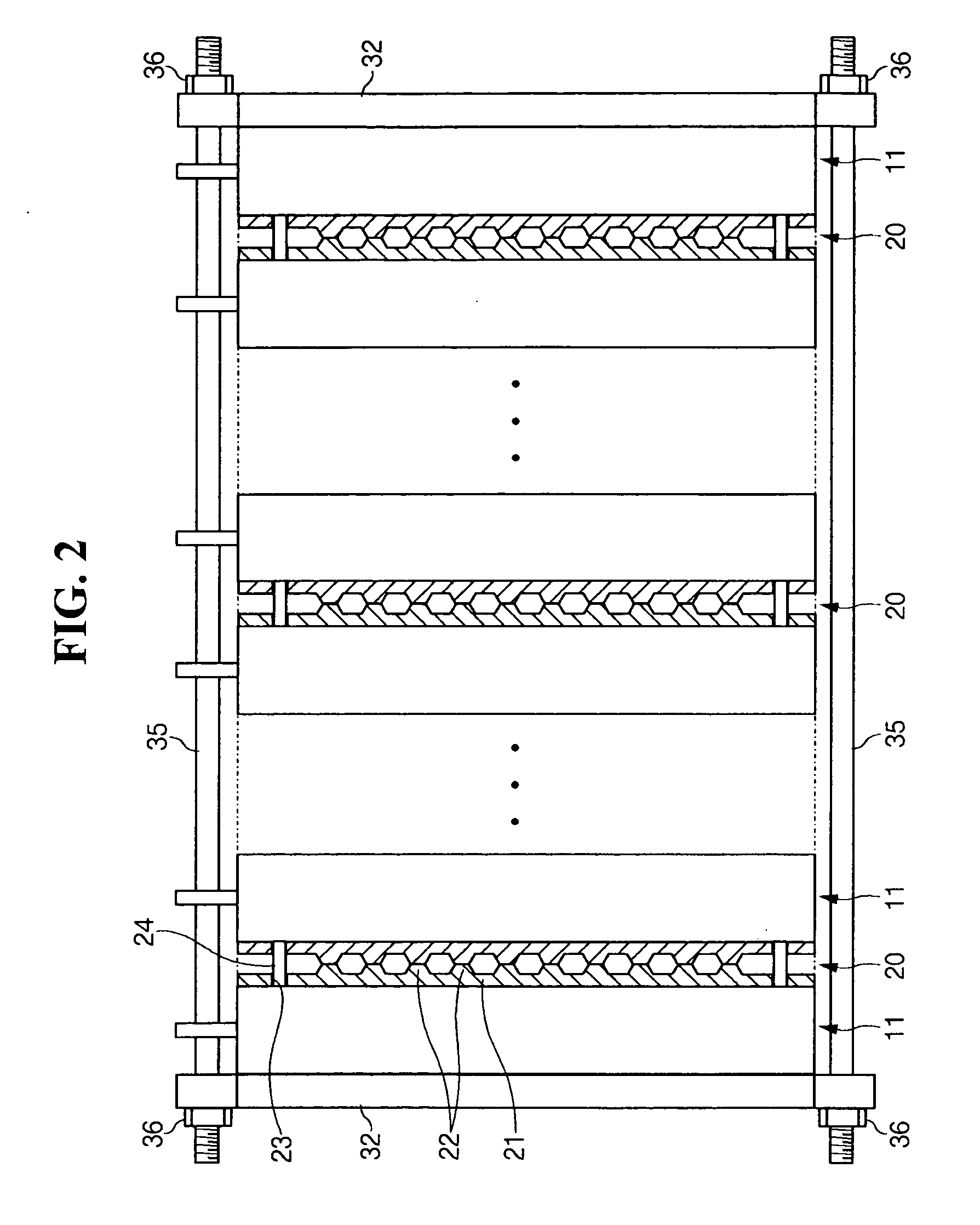
[0055]FIGS. 6 and 7 illustrate a battery module 100 according to the present invention. As shown in FIGS. 6 and 7, each barrier 20 is interposed between the unit batteries 11, and a plurality of the unit batteries 11 and the barriers 20 are arranged in series to constitute a single battery assembly. The barriers 20 allow the unit batteries to be spaced from one another at a predetermined interval and allow a cooling medium to circulate through gaps between the unit batteries.

[0056] The barrier 20 includes a pair of panels 21 that face each other. The plurality of protrusions 22 protruded on a surface of each panel 21 in a substantially constant pattern. Each corner of the panel 21 has a jointing hole 23 that extends through a thickness thereof. Both panels 21 are combined with each other through locking pins 24 that are inserted into each jointing hole 23.

[0057] The locking pins 24 each have a diameter that is slightly larger than that of the jointing holes 23, so that the locking ...


PUM


Abstract

A battery module to accurately position a barrier between unit batteries and improve constructability of a battery module, including at least two unit batteries, and at least one barrier interposed between the unit batteries. The barrier includes a pair of panels facing each other and having protrusions on a surface of each panel that faces the other panel, at least one jointing hole formed in each panel, and a locking pin inserted into the jointing hole to combine the pair of panels with each other.

Description

CROSS-REFERENCE TO RELATED APPLICATION [0001] This application claims the benefit of Korean Patent Application No. 2005-115613, filed Nov. 30, 2005 in the Korean Intellectual Property Office, the disclosure of which is incorporated herein by reference. BACKGROUND OF THE INVENTION [0002] 1. Field of the Invention [0003] Aspects of the present invention relate to a barrier and a battery module having the barrier, and, more particularly, to an improved barrier structure interposed between unit batteries and a battery module having an improved barrier structure interposed between unit batteries, by which a manufacturing process may be simplified and an effect of a manufacturing defect may be minimized. [0004] 2. Description of the Related Art [0005] A battery module includes a few or several tens of connected rechargeable batteries. The rechargeable battery may be repeatedly charged and discharged because chemical and electrical energy conversion thereof is reversible. While a low capac...

Claims


Application Information

Patent Timeline
IPC IPC(8): H01M6/42H01M50/209H01M50/291
CPCH01M2/1016H01M2/1077H01M6/46H01M10/5004H01M10/5067H01M10/5046H01M10/5055H01M10/5059H01M10/5032H01M10/6563H01M10/647H01M10/6551H01M10/6557H01M10/6555H01M10/613Y02E60/10H01M50/209H01M50/291H01M10/625H01M10/656H01M2220/20
Inventor KIM, TAE-YONGLIM, HONG-SUP
Owner SAMSUNG SDI CO LTD
Learn More