Method and device for detecting position of mobile object, and computer product

a technology for detecting the position of mobile objects and computer products, applied in the direction of navigation instruments, instruments, using reradiation, etc., can solve the problems of increasing the reducing the positioning accuracy of the gps, and not solving the gps error in the traveling direction of the vehicl

Inactive Publication Date: 2007-05-31
FUJITSU LTD
View PDF3 Cites 13 Cited by
  • Summary
  • Abstract
  • Description
  • Claims
  • Application Information

AI Technical Summary

Problems solved by technology

The positioning accuracy of GPS is sometimes significantly reduced due to an influence of multipath when the vehicle is in a location in which the radio wave from the artificial satellite is unstable, for example, when the vehicle is under elevated structures or between buildings.
However, according to map-matching explained above, a function of enhancing the positioning accuracy in the traveling direction of the vehicle regarding where the vehicle is located on the road link (or on a road link array), is not provided.
Therefore, GPS errors in the traveling direction of the vehicle are not resolved.
Furthermore, errors in the traveling direction are increased depending on the map-matching algorithm.
Therefore, the errors accumulate as the travel distance of the vehicle increases.

Method used


Image

  • Method and device for detecting position of mobile object, and computer product
  • Method and device for detecting position of mobile object, and computer product
  • Method and device for detecting position of mobile object, and computer product

Examples


first embodiment

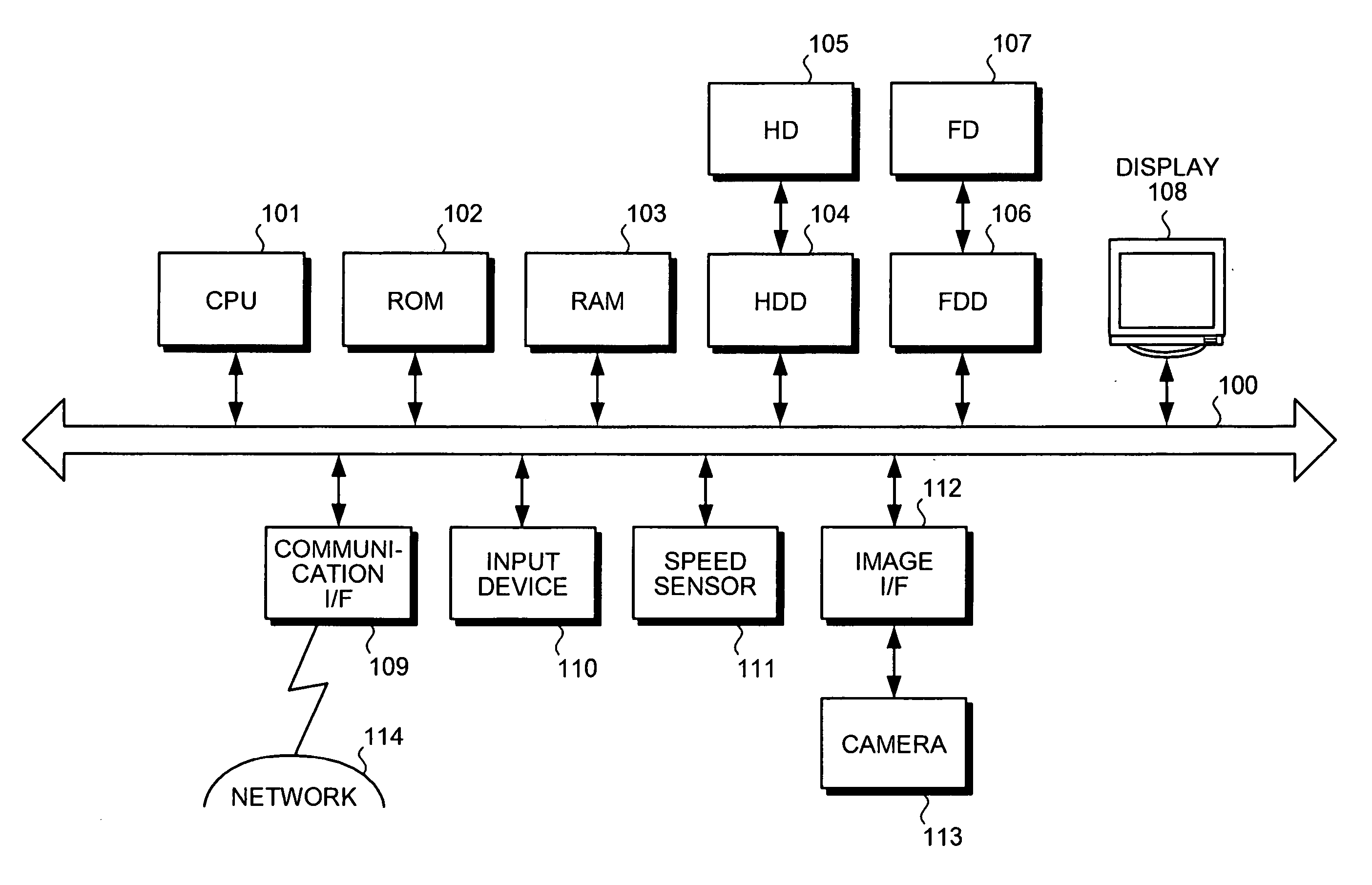
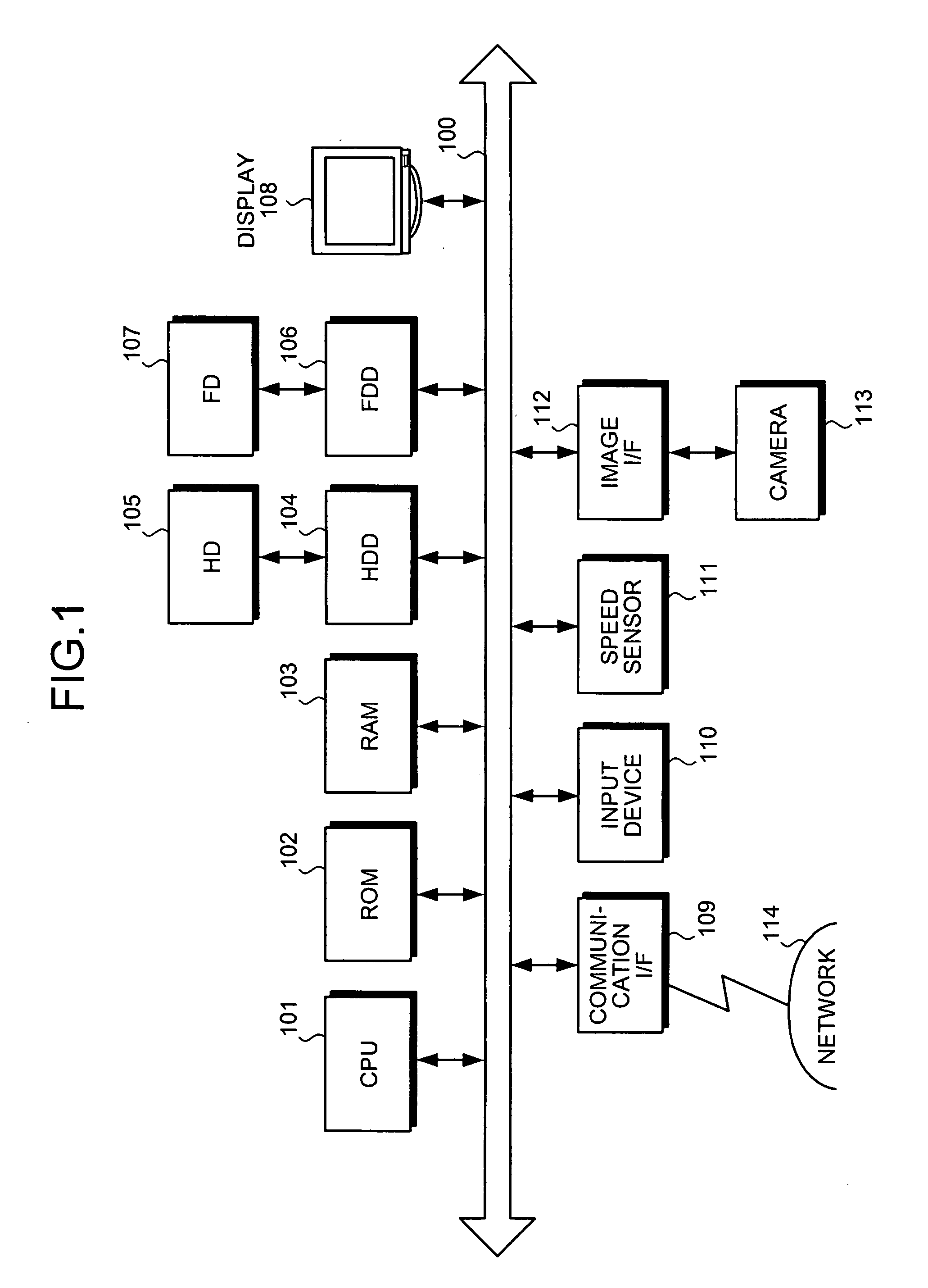
[0037]FIG. 1 is a schematic of a position detecting device according to the present invention. The position detecting device includes a central processing unit (CPU) 101, a read-only memory (ROM) 102, a random access memory (RAM) 103, a hard disk drive (HDD) 104, a hard disk (HD) 105, a flexible disk drive (FDD) 106 as an example of a removable recording medium, a flexible disk (FD) 107, a display 108, a communication interface (I / F) 109, an input device 110, a speed sensor 111, an image I / F 112, and a camera 113. Each component is connected via a bus 100.

[0038] The CPU 101 controls the entire position detecting device. The ROM 102 stores programs such as a boot program. The RAM 103 is used as a work area of the CPU 101. The HDD 104 controls reading and writing of data from and to the HD 105 under the control of the CPU 101. The HD 105 stores the data that is written into the HD 105 under the control of the HDD 104.

[0039] The FDD 106 controls reading and writing of data from and to...

second embodiment

[0109] as explained above, the processes are performed with the reference side data provided in advance. Therefore, data processing load on the device can be reduced and the position of the vehicle can be detected.

[0110] In the first embodiment, the position detection of the mobile object is performed using frame images from either the left side or the right side of the mobile object. In the third embodiment, the position detection of the mobile object is performed by the position detecting device 200 described in the first embodiment using frame images from both the left side and the right side of the mobile object.

[0111] A configuration of the position detecting device according to the third embodiment is almost the same as that in FIG. 1. The detection of the current position of the vehicle according to the third embodiment is almost the same as that in FIG. 3. A calculation of the optical flow according the third embodiment is almost the same as that in FIGS. 5A to 10. Therefo...

third embodiment

[0116]FIG. 16A is a schematic for illustrating installation of two cameras according to the Cameras 113 are installed in a vehicle 1601 traveling on an arbitrary route 1600.

[0117] The cameras 113 are installed in the directions that allow shooting from the left side and the right side of the vehicle 401. The camera 113 can shoot images in monochrome or in color, and includes the video camera or the like. The camera 113 consecutively shoots side images at intervals of several tens of frames per second. The number of frames shot per unit time is the frame rate F.

[0118]FIG. 16B is a schematic for illustrating installation of the camera and a mirror. The camera 113 and a mirror 1602 are installed in the vehicle 1601 traveling on the arbitrary route 1600.

[0119] One camera 113 is installed facing the front (or the rear) of the vehicle 1601, and can shoot the left side and the right side of the vehicle 1601 using the mirror 1602. The mirror 1602 uses an optical system such as a prism. T...


PUM


Abstract

The position detecting device includes a travel speed detecting unit, an optical flow calculating unit, a distance calculating unit, and a position detecting unit. The travel speed detecting unit detects a travel speed of a mobile object moving on an arbitrary route. The optical flow calculating unit calculates an optical flow of one side of the mobile object, based on a series of frame images of the one side. The one side is any one of a left side and a right side of the mobile object. The distance calculating unit calculates a distance to a subject on the one side based on the travel speed and the optical flow. The position detecting unit detects a current position of the mobile object based on point data of the subject and the distance to the subject.

Description

CROSS-REFERENCE TO RELATED APPLICATIONS [0001] This application is based upon and claims the benefit of priority from the prior Japanese Patent Application No. 2005-342623, filed on Nov. 28, 2005, the entire contents of which are incorporated herein by reference. BACKGROUND OF THE INVENTION [0002] 1. Field of the Invention [0003] The present invention relates to a technology for detecting a current position of a mobile object based on a series of frame images of a left side and a right side of the mobile object. [0004] 2. Description of the Related Art [0005] Conventionally, a navigation device installed in a mobile object such as a vehicle provides a navigation service to a driver by measuring a position of the vehicle using a global positioning system (GPS). GPS performs positioning based on an arrival time of a radio wave transmitted from an artificial satellite. GPS has a positioning accuracy of several meters to several tens of meters. Further increase in the positioning accura...

Claims


Application Information

Patent Timeline
Patent Type & Authority Applications(United States)
IPC IPC(8): G01C21/00
CPCG01S11/12G01S19/45G01S19/50G06T7/0071G06T7/579
Inventor SHIMIZU, SEIYAKITAURA, ASAKOMIZUTANI, MASAMI
Owner FUJITSU LTD
Why Eureka
Try Eureka