Thermal flowmeter of fluid
a flowmeter and fluid technology, applied in the direction of volume/mass flow measurement, measurement devices, instruments, etc., can solve the problems of deteriorating measurement accuracy, deteriorating measurement accuracy, and deteriorating accuracy, so as to reduce errors in measurement accuracy and improve the accuracy of flow rate measuremen
- Summary
- Abstract
- Description
- Claims
- Application Information
AI Technical Summary
Benefits of technology
Problems solved by technology
Method used
Image
Examples
first embodiment
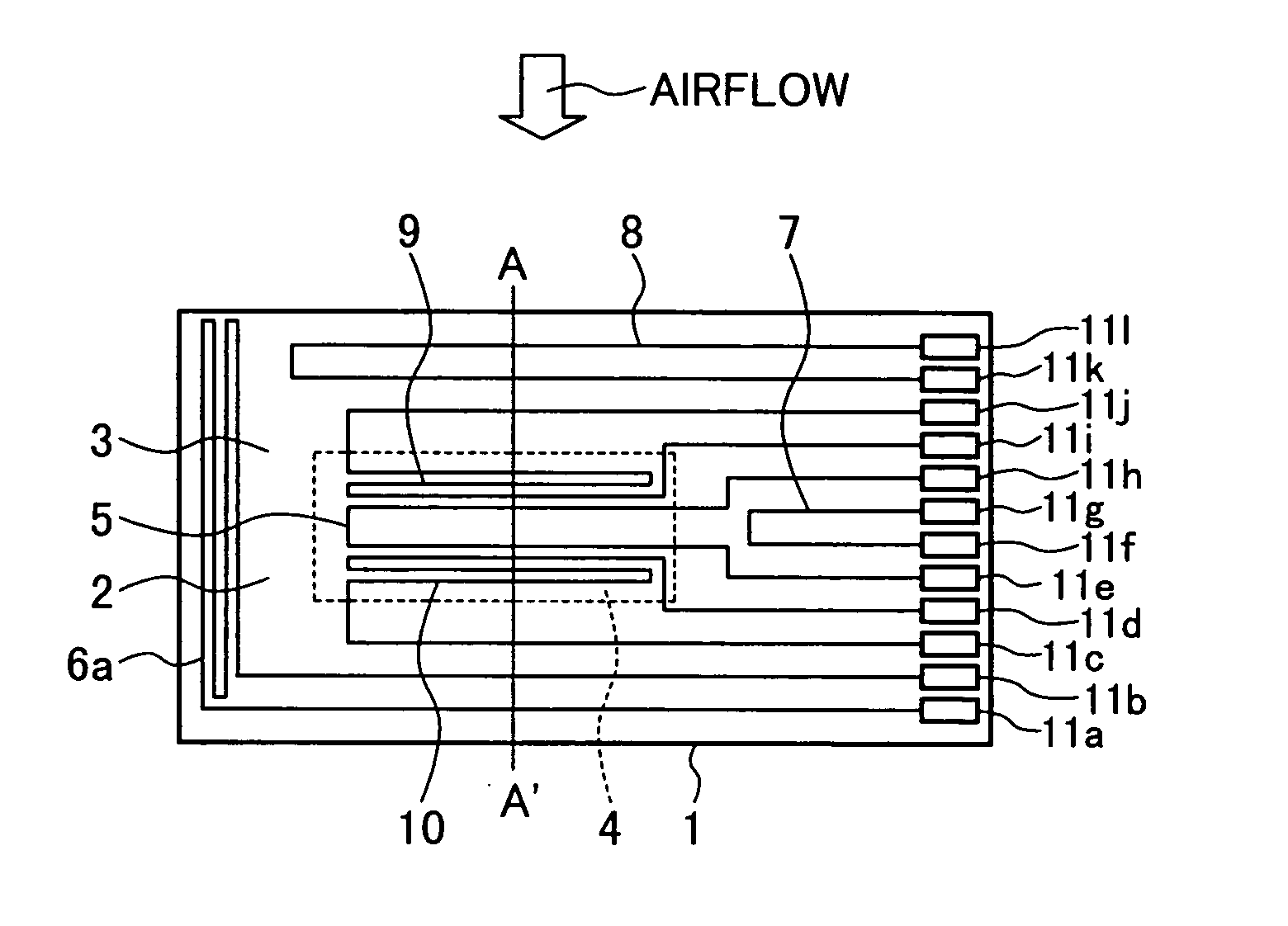
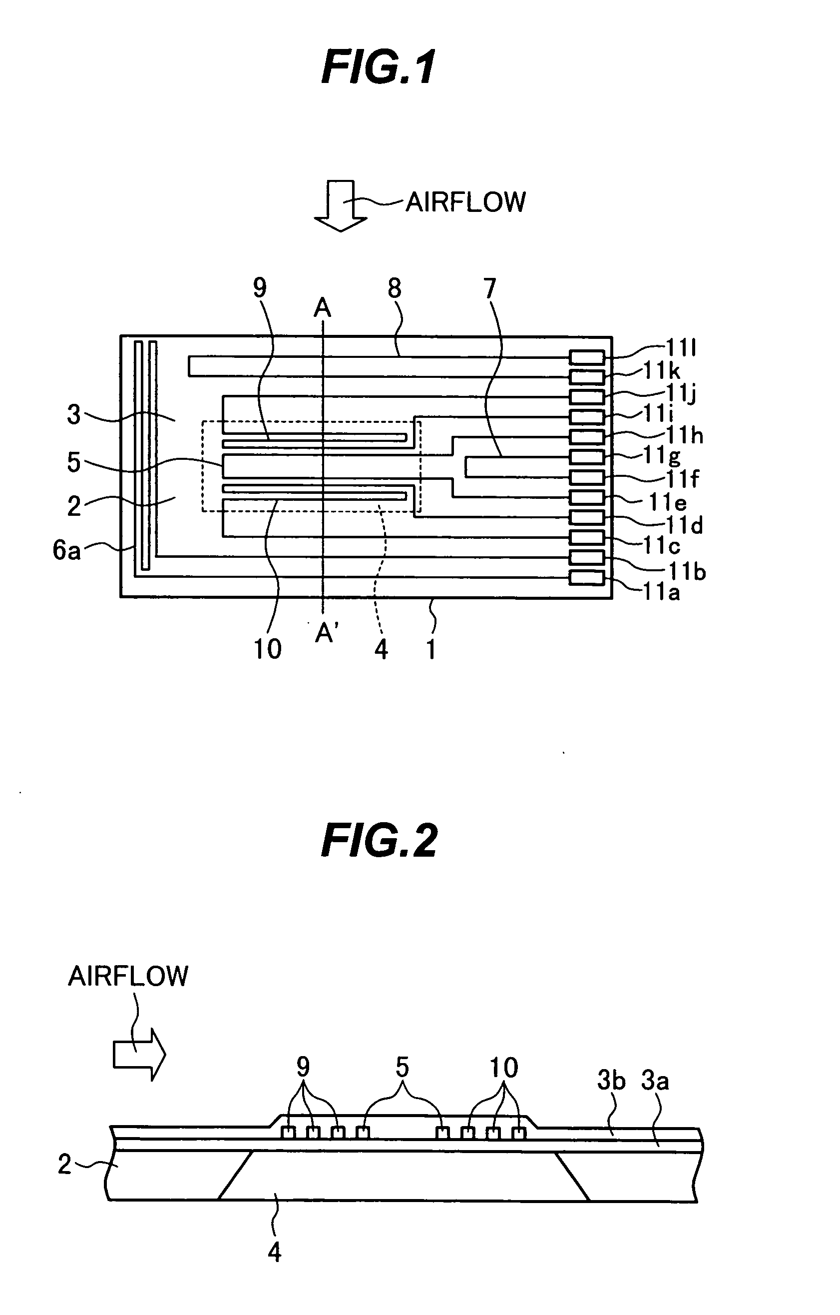
[0041]FIG. 1 is a plan view showing a measuring element of a thermal air flowmeter according to the present invention. FIG. 2 is a sectional view of the measuring element taken along the line A-A′ in FIG. 1.
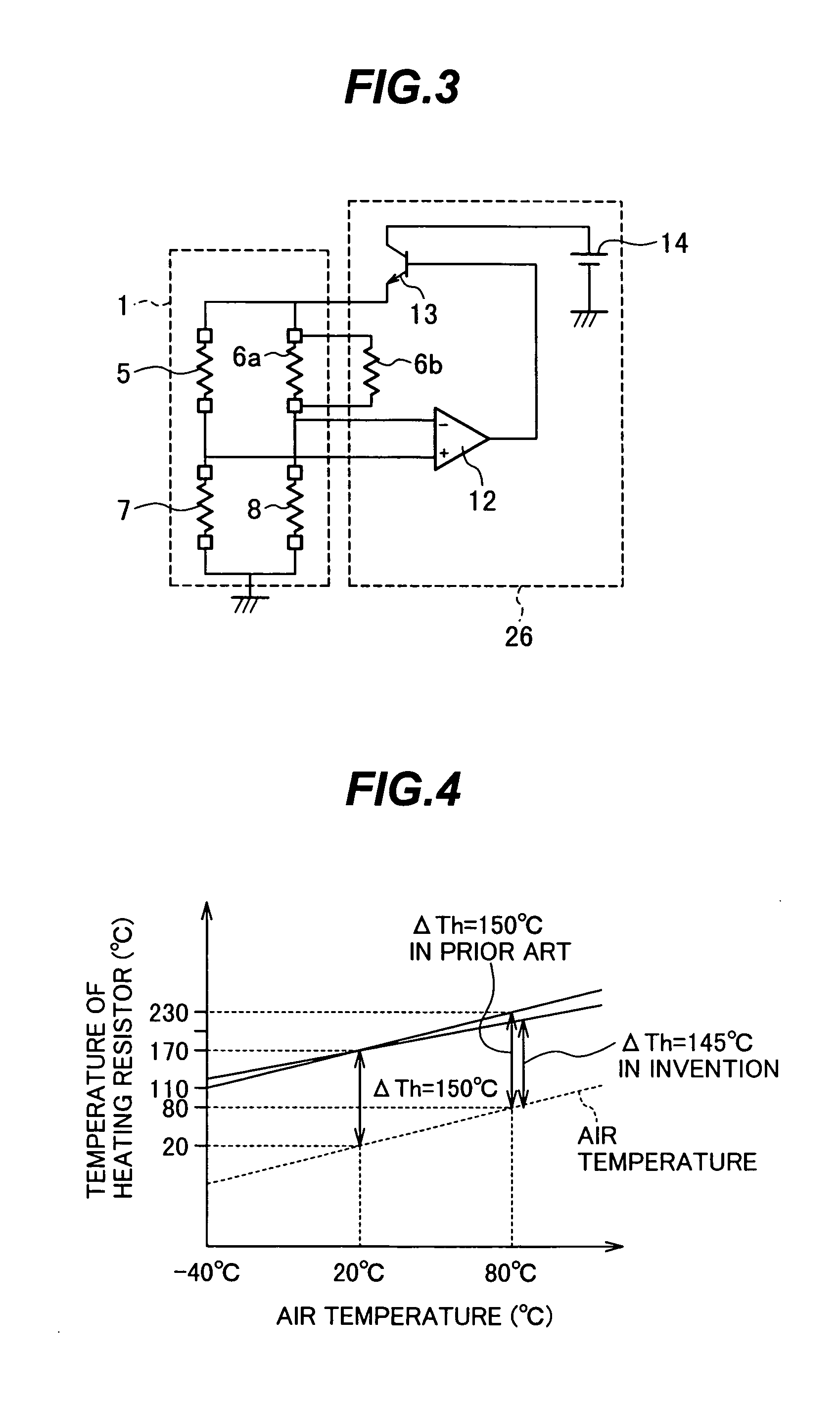
[0042] Referring to FIGS. 1 and 2, a measuring element 1 comprises a semiconductor substrate 2 made of, e.g., silicon and having a cavity 4 formed by anisotropic etching to extend upward from a lower surface of the substrate to a boundary with respect to an electric insulating film 3a, and a heating resistor 5 formed on the electric insulating film 3a that covers the cavity 4. The measuring element 1 further comprises a temperature compensation resistor 6a for performing temperature compensation of the heating resistor 5, a first resistor 7, and a second resistor, the first and second resistors forming a bridge circuit in combination with the heating resistor 5 and the temperature compensation resistor 6a.
[0043] On the measuring element 1, a first temperature measuring resistor ...
second embodiment
[0101]FIG. 15 is a diagram showing a drive circuit for the heating resistor 5 in the present invention. This drive circuit supplies a current to the heating resistor 5 on the measuring element 1 and performs heating temperature control.
[0102] The drive circuit shown in FIG. 15 differs from the drive circuit shown in FIG. 3 in that the resistor 6b is connected to the resistor 6a in parallel in the example of FIG. 3, while a resistor 29 is connected to the resistor 7 in parallel in the example of FIG. 15 instead of connecting the resistor 6b to the resistor 6a. The other arrangement in the example of FIG. 15 is the same as that in the example of FIG. 3.
[0103] Referring to FIG. 15, the heating resistor 5, the temperature compensation resistor 6a, the first resistor 7, and the second resistor 8, which are formed on the measuring element 1, are all made of the same resistor material, while the fixed resistor 29 is made of a different resistor material from that used for the resistors 5,...
third embodiment
[0107]FIG. 16 is a diagram showing a flow rate detection circuit according to the present invention.
[0108] Referring to FIG. 16, the flow rate detection circuit comprises a first temperature measuring resistor 9 for detecting the flow rate, a second temperature measuring resistor 10 connected to the first temperature measuring resistor 9 in series, the first and second temperature measuring resistors 9, 10 being made of the same resistor material (polysilicon resistor), and a fixed resistor 30 connected to the resistor 10 in parallel and made of a material (having the resistance temperature coefficient=about 0 ppm / ° C.) different from that of the resistors 9 and 10. The fixed resistor 30 may be connected to the second temperature measuring resistor 10 in series.
[0109]FIG. 17 is a graph showing dependency of a flow rate detection voltage upon the air temperature at a flow rate of 0 kg / h.
[0110] As shown in FIG. 17, because the flow rate detection circuit of the prior art is a serial...
PUM
 Abstract
Description
Claims
Application Information
 - R&D
- Intellectual Property
- Life Sciences
- Materials
- Tech Scout
- Unparalleled Data Quality
- Higher Quality Content
- 60% Fewer Hallucinations
Browse by: Latest US Patents, China's latest patents, Technical Efficacy Thesaurus, Application Domain, Technology Topic, Popular Technical Reports.
© 2025 PatSnap. All rights reserved.Legal|Privacy policy|Modern Slavery Act Transparency Statement|Sitemap|About US| Contact US: help@patsnap.com


