Cutter

a paper cutter and cutting board technology, applied in the field of paper cutters, can solve problems such as unnecessary damage to paper pieces, and achieve the effect of simple structure and reliably avoiding troubl

Inactive Publication Date: 2007-06-07
ASKA
View PDF18 Cites 31 Cited by
  • Summary
  • Abstract
  • Description
  • Claims
  • Application Information

AI Technical Summary

Benefits of technology

[0005] It is a main object of the present invention to use a simple structure to reliably avoid trouble wherein the cutting edge of a rotary blade, which is

Problems solved by technology

However, this paper cutter has caused problems in, e.g., that when the holder is pushed downward in a case wherein the guide is not slanted, the blade is protruded, and that when the holder is i

Method used


Image

  • Cutter
  • Cutter
  • Cutter

Examples


Embodiment Construction

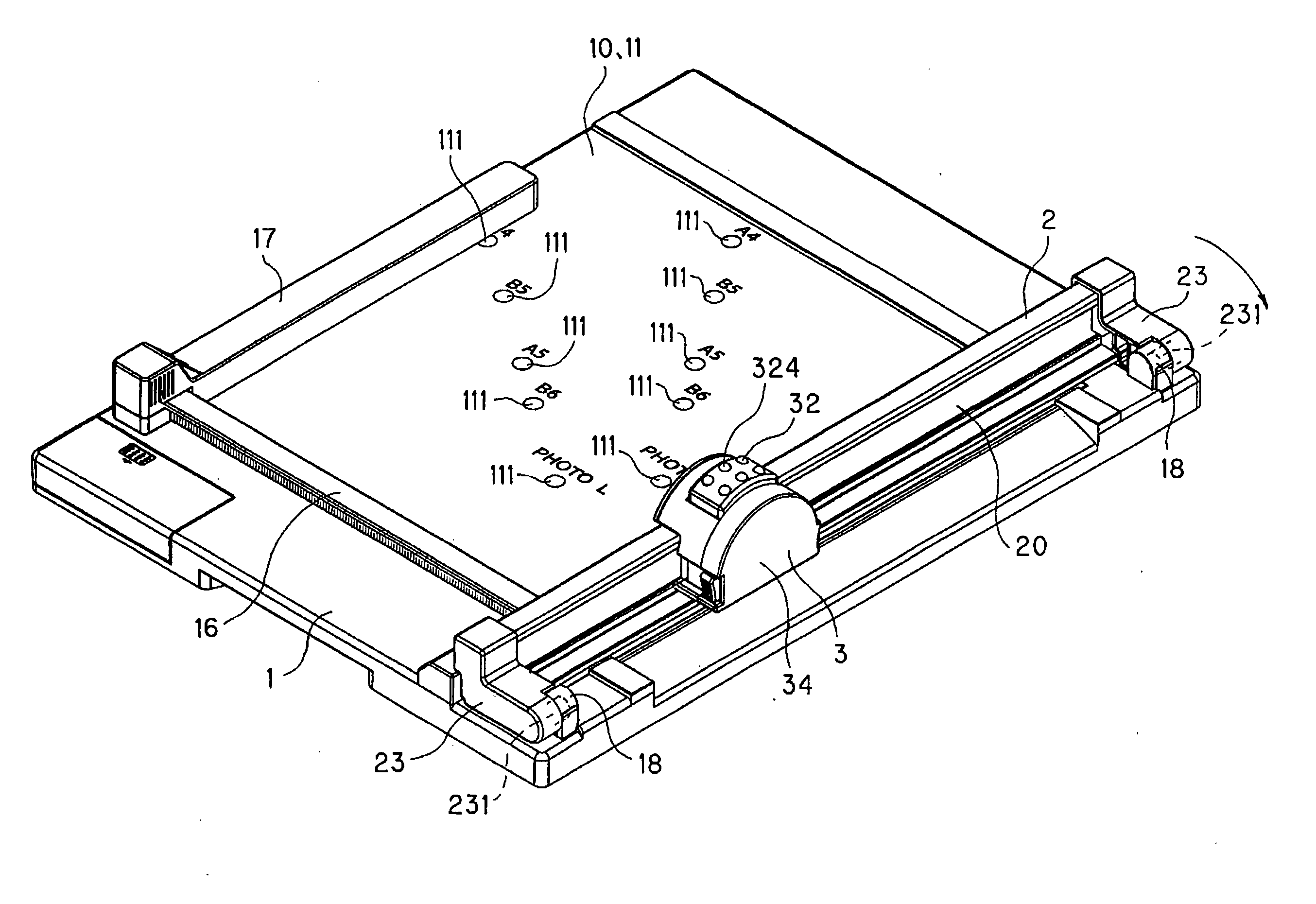
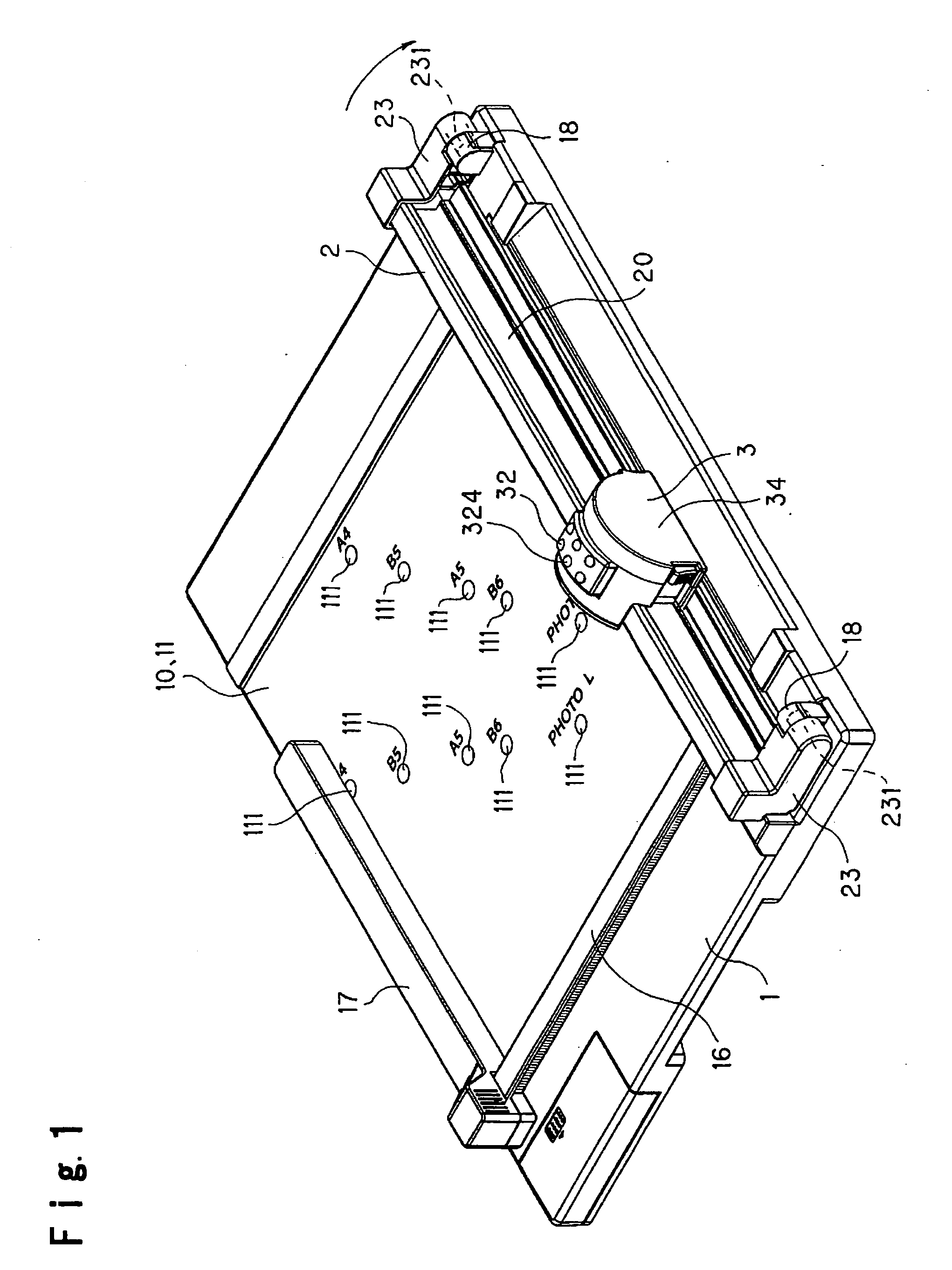
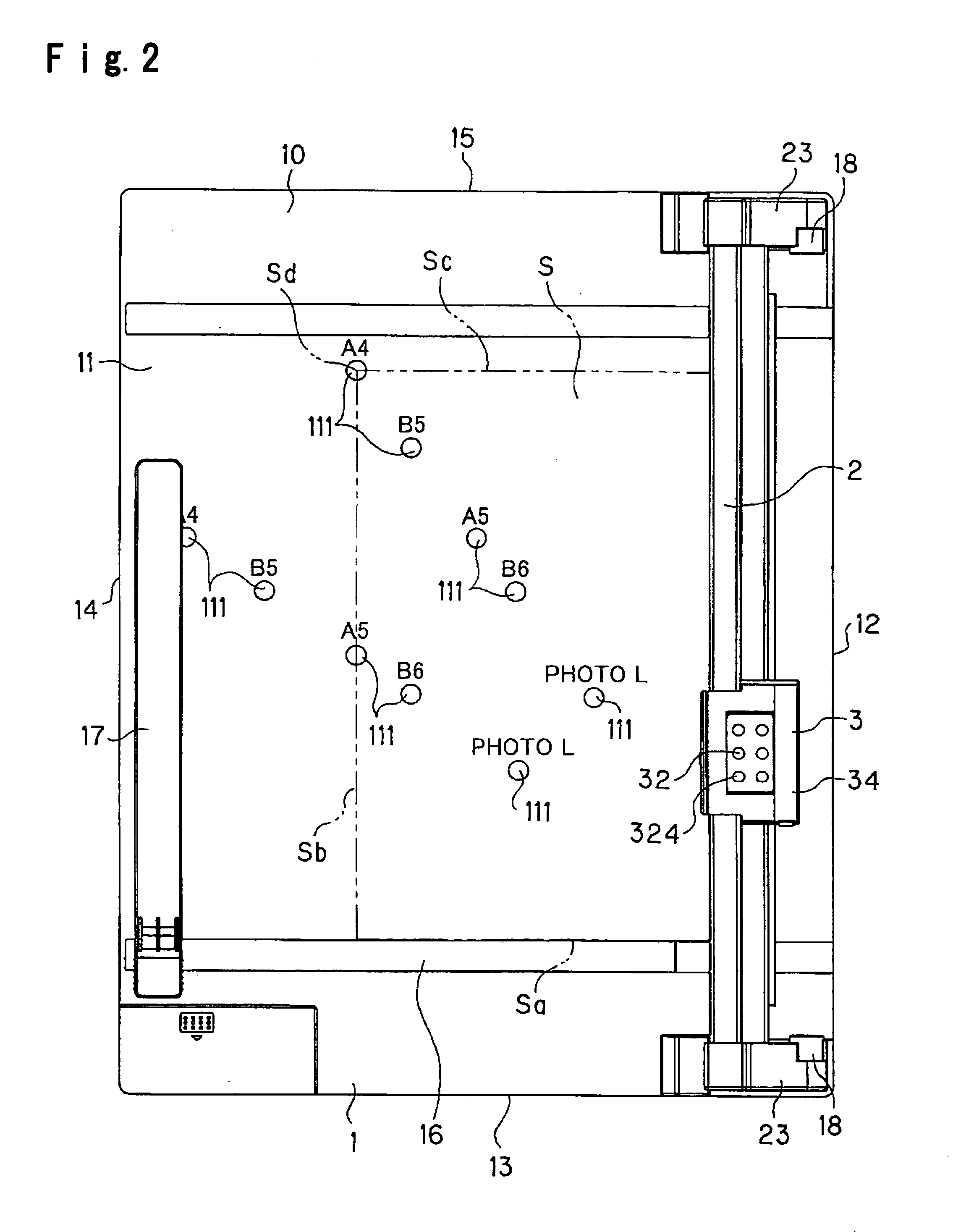
[0077] Now, preferred embodiments of the present invention will be described, referring to FIGS. 1 to 25.

[0078]FIGS. 1 and 2 show the entire structure of the paper cutter according to an embodiment of the present invention. FIGS. 3 and 4 show the paper cutter in vertical cross-sectional views at a position with a slider 3 disposed thereat in order to easily understand the internal structure of the slider having a rotary blade 30. FIGS. 5 and 6 show a state wherein the slider has a slider cover 34 removed from a slider base 31. FIG. 7 shows a state wherein the rotary blade 30 is replaced with a new one by use of a replacement tool 4 with the slider cover 34 being removed. FIG. 8 shows parts forming the replacement tool 4 in a disassembled state. FIGS. 9 and 10 show parts forming the slider 3 in a disassembled state. FIG. 11 shows essential parts of the slider 3 in a disassembled state in order to easily understand the positional relationship between a slider lock 314 and a locking s...


PUM

PropertyMeasurementUnit
Forceaaaaaaaaaa

Abstract

A slider base has a slider lock combined therewith so as to be selectively and laterally displaced between a locked position and an unlocked position. The mount has a passage formed therein so as to receive a leg portion of the slider lock, the passage including a locking shoulder formed between an upper compartment and a lower compartment so as to face downward. When the slider is set in the locked position, the leg portion of the slider lock is located under the locking shoulder, and when the slider is set in the unlocked position, the leg portion of the slider lock is located so as to be capable of being inserted into the upper compartment by depressing the mount toward a lower position against an urging force of an urging device.

Description

BACKGROUND OF THE INVENTION [0001] The present invention relates to an improvement in a paper cutter, which is used for easily and correctly cutting a sheet-like object to cut, such as a piece of paper, in order to set such a sheet-like object into a desired size or remove an unwanted part of such a sheet-like object. BACKGROUND ART [0002] JP-A-11-333792 has disclosed a paper cutter, which includes a guide rail swingably assembled to a paper stand, and a slider with a blade, the slider being disposed so as to be slidable on the guide rail, and which can cut a piece of paper sandwiched between the guide rail and the paper stand by moving the slider along the guide rail in such a state that the slider is shifted toward the paper stand against an urging force of a spring to protrude the blade. [0003] This paper cutter includes a stopper, which is engaged with a projection when the guide rail is slanted, the projection formed on a blade holder in the slider. By this arrangement, the bla...

Claims


Application Information

Patent Timeline
IPC IPC(8): B26D1/18B23D19/00
CPCB26D1/205B26D7/015B26D7/025B26D7/20B26D7/22B26D7/2621B26D2007/0087Y10T83/7507Y10T83/7763Y10T83/7784Y10T83/8822
Inventor DONG, WU XIAOTOYAMA, YUJI
Owner ASKA
Why Eureka
Try Eureka