Die, manufacturing method of a laser disk, and a laser disk
Inactive Publication Date: 2007-06-07
PANASONIC CORP
View PDF0 Cites 4 Cited by
Summary
Abstract
Description
Claims
Application Information
AI Technical Summary
This helps you quickly interpret patents by identifying the three key elements:
Problems solved by technology
Method used
Benefits of technology
Benefits of technology
[0027] As described above, conventionally, the intermediate layer 103, which is interposed between the first recording layer 102 and the second recording layer 104, is formed by sticking the ultraviolet-curing resin 109 on the adhesive 107 of the disk substrate 101. It is necessary to form the respective layers forming the optical disk such as the intermediate layer 103 as well as the cover layer 105 and the rear-side coat layer 106 with smaller thickness, with more uniform film quality and film thickness in a plane, and at lower cost compared with those in the past.
[0047] Taking the conventional problems into account, it is an object of the present invention to manufacture a layer having more uniform thickness distribution or provide a die which can be manufactured at lower cost, a method of manufacturing an optical disk using the die, and an optical disk.
[0065] According to the present invention, it is possible to manufacture a layer having more uniform thickness distribution or provide a die which can be manufactured at lower cost, a method of manufacturing an optical disk using the die, and an optical disk.
Problems solved by technology
In a lens having a higher NA, blur and aberration tend to occur.
Method used
Image
Click on the blue label to locate the original text in one second.
Reading with bidirectional positioning of images and text.
Examples
first embodiment
[0120] A coating device in a first embodiment according to the present invention will be explained and an example of a die of the present invention will be simultaneously explained.
[0121] First, a structure of a blu-ray disk, which is an example of an optical disk of the present invention manufactured by using the coating device in the first embodiment, will be explained.
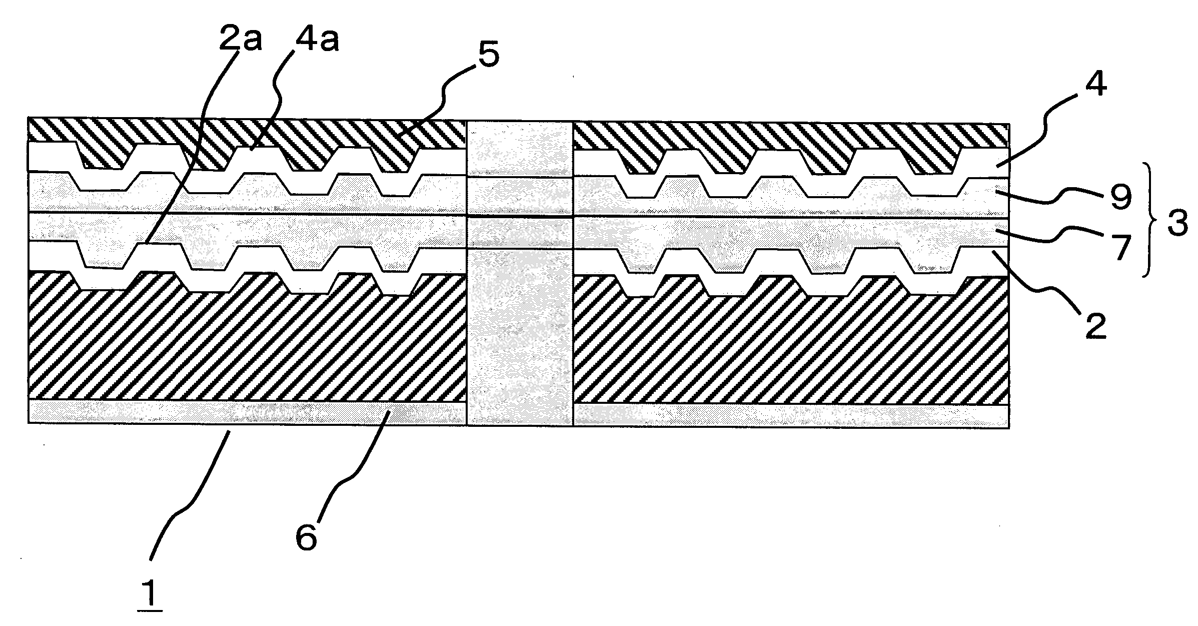
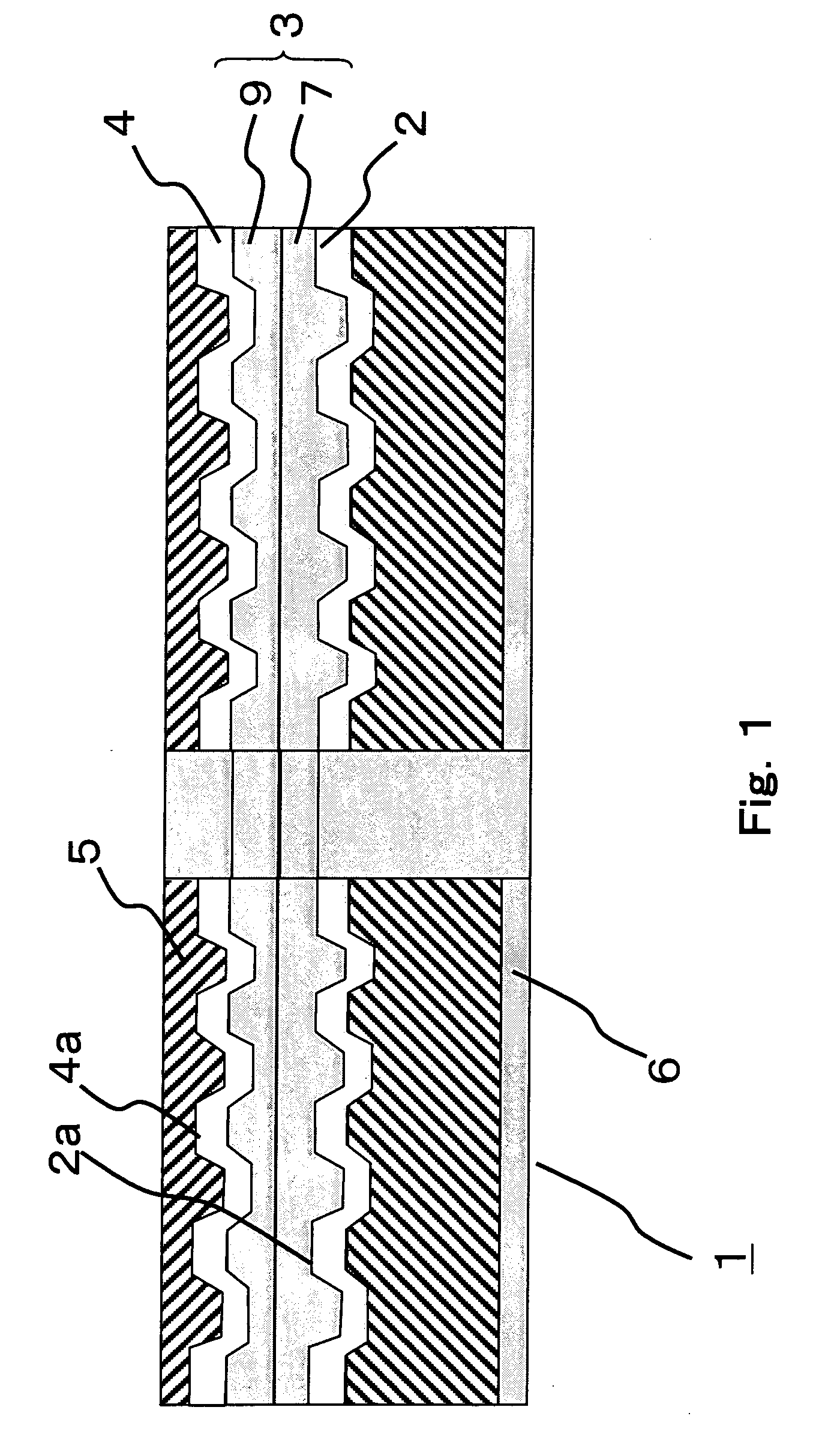
[0122] The blu-ray disk uses a blue laser having a wavelength of about 405 nm for reading and writing. This blu-ray disk is a two-layer disk. FIG. 1 is a diagram of the blu-ray disk. This blu-ray disk has the same structure as the two-layer disk explained with reference to FIG. 19 earlier.
[0123] As shown in FIG. 1, in the blu-ray disk, a first recording layer 2 having a recording track 2a is formed on a disk substrate 1. A second recording layer 4 having a recording track 4a is formed on the first recording layer 2 via an intermediate layer 3. A cover layer 5 which covers the second recording layer 4 is formed. A...
first example
[0157]FIG. 11A is a perspective view of a die 60 in the first example. FIG. 11B is a plan view of the die 60 viewed from an arrow I direction in FIG. 11A. FIG. 11C is a top view of a lower block 12′. As shown in FIG. 11C., the die 60 in the first example is different from the die 27 explained in the first embodiment in that the slit length 16 is fixed in the width 17 direction (Lsa=Lsc=Lsb). On the other hand, the slit gap 15 formed by the upper block 11 and the lower block 12′ monotonously increases from one end to the other end along the width 17 direction as in the first embodiment. As respective lengths of the die 60 in the first example, Lsa=Lsb=Lsc=20 mm, hsa=100 μm, and hsb=60 μm. A ratio of hsb and hsa is 3:5.
[0158] A discharge quantity of a paint is affected by a pressure loss in the slit portion and a pressure loss ΔPs is in an inversely proportional relation with the cube of the slit gap hs (ΔPs∝(1 / (hs×hs×hs)). Thus, it is considered that, in order to increase a discharg...
second example
[0164] In the second example, the die 27 described in the first embodiment was used. As the respective lengths of the die 27, Lsa=Lsb=20 mm, Lsc=15 mm, hsa=100 μm, and hsb=60 μm. The die 27 in the second example is different from the die 60 in the first example in that the length of the slit length 16 is small in the center of the width 17. As ratios of the length, hsb:hsa is 3:5 and Lsc:Lsa is 3:4.
[0165] As in the first example, the die in the second example was opposed to a container provide with thin partitions at intervals of 2 mm such that the partitions divided the discharge port 18 of the die at the intervals of 2 mm in the width 17 direction. In this state, after resin was discharged from the die in the second example for thirty seconds, a discharge quantity distribution in the width 17 direction was measured by measuring weight of the resin accumulated in the respective partitions. A result of the measurement is shown in a graph of a discharge quantity distribution in FIG....
PUM
Abstract
The die as provided is a die in which an upper block is placed on an upper surface of a lower block with a lower surface of the upper block in contact with the upper surface, wherein the lower block includes a manifold and a slit serving as a path for discharging paint from the manifold to the outside, constituted respectively from between the lower block and the lower surface of the upper block by forming a cavity and a space which communicates with the outside from this cavity along a columnar direction, respectively, from one end face of a columnar body with a trapezoidal shape of cross section to the other end face, a paint supply path which communicates with the manifold is formed from an outer side located between the one end face and the other end face of the lower block, a slit space dimension of the slit between front end portions in a paint discharge direction of the lower block and the upper block in a discharge port serving as an open end to the outside is smallest on the one end face side and increases toward the other end face side, and a slit length which is a dimension along the paint discharge direction of a space forming surface of the lower block constituting the slit is largest on at least one of the one end face side and the other end face side and is smallest in a position between both the end faces.
Description
CROSS-REFERENCE TO RELATED APPLICATIONS [0001] This application claims priority to Japanese Patent Application No. 2005-283047, filed in the Japanese Patent Office on Sep. 28, 2005, the entire contents of it are hereby incorporated herein by reference. BACKGROUND OF THE INVENTION [0002] 1. Field of the Invention [0003] The present invention relates to a die for forming a resin layer as an intermediate layer of an optical disk or a coat layer of a front surface or a rear surface of the optical disk, a method of manufacturing an optical disk, and an optical disk. [0004] 2. Related Art of the Invention [0005] A general structure of a conventional optical disk will be explained. In recent years, there have been remarkable increases in a recording density and a capacity of optical disks used for various applications for information recording such as audios, images, and computers. Products such as CDs (compact disks) and DVDs (digital versatile disks) have been produced. In general, such ...
Claims
Application Information
Patent Timeline
Application Date:The date an application was filed.
Publication Date:The date a patent or application was officially published.
First Publication Date:The earliest publication date of a patent with the same application number.
Issue Date:Publication date of the patent grant document.
PCT Entry Date:The Entry date of PCT National Phase.
Estimated Expiry Date:The statutory expiry date of a patent right according to the Patent Law, and it is the longest term of protection that the patent right can achieve without the termination of the patent right due to other reasons(Term extension factor has been taken into account ).
Invalid Date:Actual expiry date is based on effective date or publication date of legal transaction data of invalid patent.

