Assembly and method for providing an interlocking angular end joint

a technology of angular end joints and end joints, which is applied in the direction of adhesive application devices, manufacturing tools, and dovetail work, etc., can solve the problems of poor results in high-end millwork applications, poor quality of end joinery provided by factory end joiners, and insufficient availability of most wood species in wide widths and long lengths to adequately satisfy demand, etc., to achieve easy machining and assembly, and increase the strength of end joined boards

Inactive Publication Date: 2007-06-07
ABBOTT RICHARD T
View PDF8 Cites 19 Cited by
  • Summary
  • Abstract
  • Description
  • Claims
  • Application Information

AI Technical Summary

Benefits of technology

[0015] The present invention provides the following advantages: (1) the capabilities to end join relatively short lengths into long lengths wherein the joint becomes virtually invisible after machining a moulding profile; (2) the ability to fabricate lengths of boards beyond the standard available lengths, thereby providing long lengths of moulding without the appearance of an end joint; (3) the ability to make long lengths of boards out of species of lumber for which long lengths are not commercially available; (4) the capability of increasing the strength of the end joined boards to withstand changes in temperature and humidity at the job site or final application; and (5) the ability to provide a very strong end joint with relatively easy machining and assembly that by the nature of its design renders the visibility of the end joint virtually impossible to visually detect.

Problems solved by technology

Unfortunately, most wood species are not abundantly available in wide widths and long lengths to adequately satisfy demand.
Prior-art methods of “jobsite” and factory end joinery provide poor results in high end millwork applications and are generally aesthetically unacceptable.
Prior-art methods are plagued with problems, such as readily visible joints, whether painted or stained and very weak joints that open and close with changes of temperature and humidity.
However, the end joints are highly visible and aesthetically unacceptable in premium stain grade woodwork applications.
Additionally, present and past methods of “jobsite” end joinery produce open gaps and uneven appearances that are easily visible, unsightly and unacceptable.
However, these scarf joints are deficient and impractical.
The disadvantages are numerous and include at least: (1) inadequate glue surface area created by the scarf joint to provide a strong joint; (2) the scarf joint has no mechanical interlock; (3) the scarf joint is extremely difficult to join reliably with common machining methods and adhesives; and (4) the scarf joint is an unreliable joint due to inherent movement (cupping, curling, and twisting) of wood due to differing grain direction and characteristics in the pieces to be joined, in addition to temperature and moisture changes.

Method used


Image

  • Assembly and method for providing an interlocking angular end joint
  • Assembly and method for providing an interlocking angular end joint
  • Assembly and method for providing an interlocking angular end joint

Examples


Embodiment Construction

[0025] Reference will now be made to the following detailed description of the preferred and alternate embodiments of the present invention. Those skilled in the art will recognize that the present invention provides many inventive concepts and novel features, that are merely illustrative, and are not to be construed as restrictive. Accordingly, the specific embodiments discussed herein are given by way of example and do not limit the scope of the present invention.

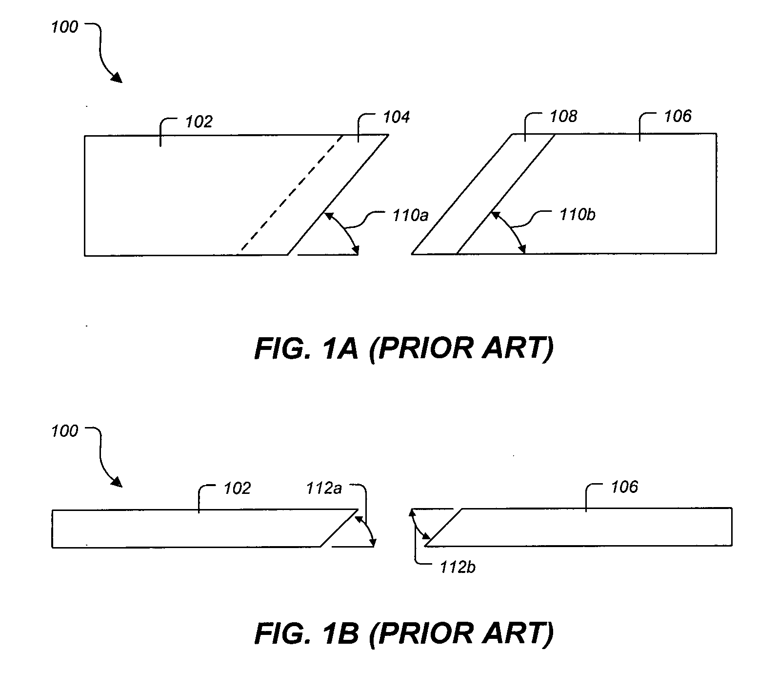
[0026] Referring now to FIGS. 1A and 1B in the drawings, an end joint 100 according to the prior art is illustrated. Prior-art end joint 100 includes a first portion 102, a first scarf joint face 104 angularly inclined to the width of first portion 102 at an angle 110a, a second portion 106, a second scarf joint face 108 angularly inclined to the width of second board portion 106 at an angle 110b. First scarf joint face 104 and second scarf joint face 108 further includes a first angular incline 112a and a second angular...


PUM


Abstract

An assembly and method is disclosed for providing an interlocking angular end joint. The interlocking angular end joint is capable of providing a virtually invisible end joint and comprises at least a first board capable of being longitudinally ripped from lumber to a predetermined width, at least a first angle cut at a predetermined angle into at least one end portion relative to the longitudinal length of the first board, and at least a first interlocking member capable of being machined into at least one end portion of the first board.

Description

BACKGROUND [0001] 1. Field of the Invention [0002] The present invention relates generally to the end joining of lumber and, more specifically, to an assembly and method for providing a unique interlocking joint in lumber and moulding. [0003] 2. Description of Related Art [0004] High end moulding and millwork have always been a prized architectural feature of fine residences, professional offices, restaurants, and institutional buildings. Unfortunately, most wood species are not abundantly available in wide widths and long lengths to adequately satisfy demand. [0005] Prior-art methods of “jobsite” and factory end joinery provide poor results in high end millwork applications and are generally aesthetically unacceptable. Prior-art methods are plagued with problems, such as readily visible joints, whether painted or stained and very weak joints that open and close with changes of temperature and humidity. [0006] Present and past methods of factory end joinery have focused on saving lu...

Claims


Application Information

Patent Timeline
Patent Type & Authority Applications(United States)
IPC IPC(8): B27C9/00B27F1/00B27D1/00B27G11/00B27M1/08
CPCB27F1/16B27M1/08B27M3/002
Inventor ABBOTT, RICHARD T.
Owner ABBOTT RICHARD T
Why Eureka
Try Eureka