
High strength spring steel wire with excellent coiling properties and hydrogen embrittlement resistance

a coiling technology, applied in the field of high-strength spring steel wire, can solve the problems of increasing material costs, deteriorating workability, and difficulty in improving the strength of steel, and achieves enhanced hydrogen embrittlement resistance, high strength, and effective coiling operation

Inactive Publication Date: 2007-06-07
KOBE STEEL LTD
View PDF6 Cites 25 Cited by
  • Summary
  • Abstract
  • Description
  • Claims
  • Application Information

AI Technical Summary

Benefits of technology

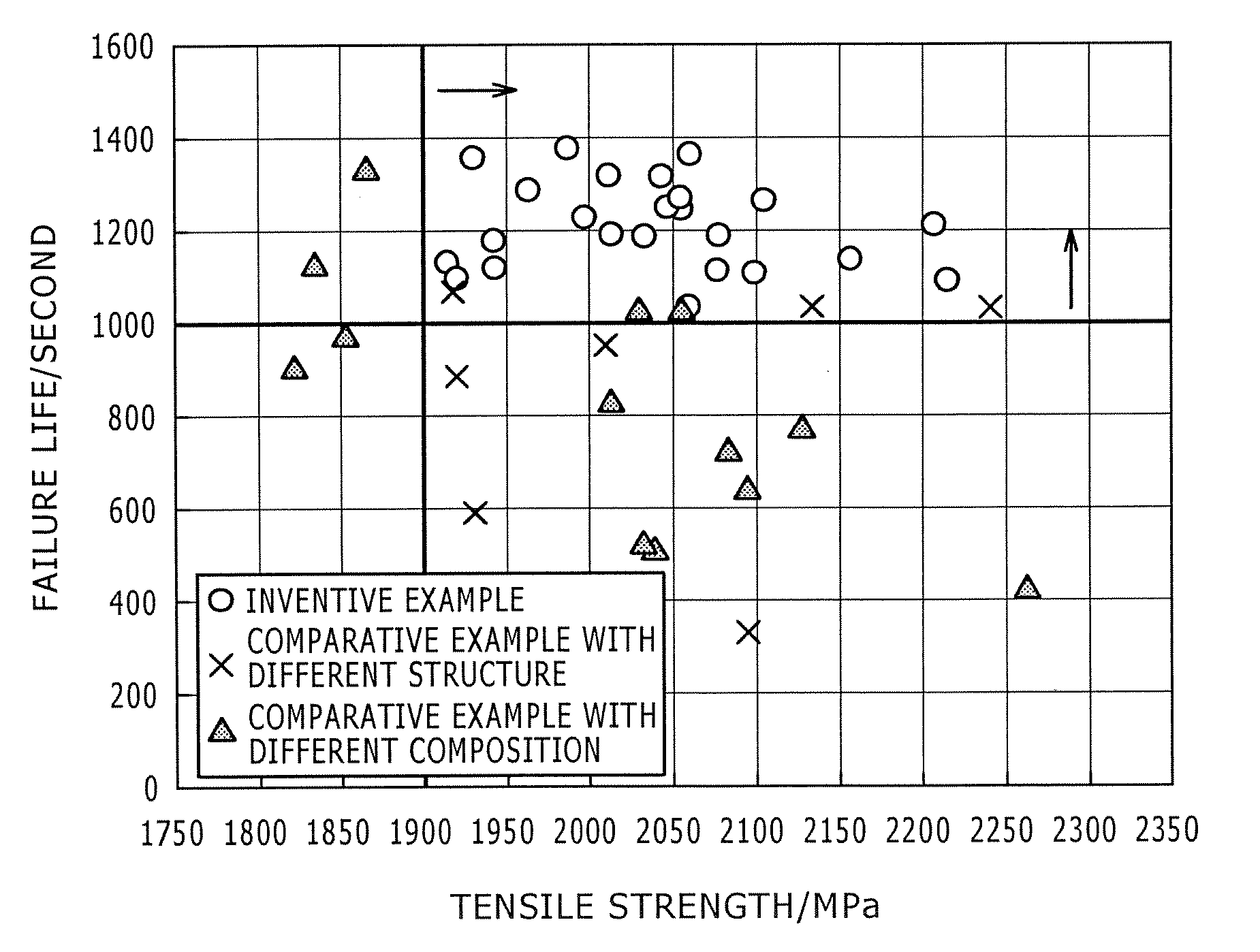
[0023] The present invention has been made to solve the above problems, and it is an object of the present invention to provide a high strength spring steel wire, which has a tensile strength of 1,900 MPa or more, and has enhanced coiling properties and hydrogen embrittlement resistance such that the steel wire may be suitably applied to a process of manufacturing a cold wound coil spring. Here, it is needless to say that the steel wire of the present invention may be applied to a process of manufacturing a hot wound coil spring.
[0026] As apparent from the above description, according to the present invention, the high strength spring steel wire permits an effective coiling operation in a process of cold spring winding as well as a process of hot spring winding, and has enhanced hydrogen embrittlement resistance and a tensile strength of 1,900 MPa or more. As a result, a suspension spring and the like having high strength as automobile parts, hardly causing delayed failure and the like can be supplied at a low cost.

Problems solved by technology

However, since increase in strength of steel generally enhances atmospheric fatigue properties while reducing corrosion fatigue properties, it is difficult to improve both atmospheric fatigue properties and corrosion fatigue properties together with the strength of the steel.
However, according to these methods, an increase in required level results in an increase of added amounts of alloy elements, thereby increasing material costs while deteriorating workability.
However, for the process of manufacturing the cold-wound coil spring, since the spring winding is performed after the quenching and tempering unlike the process of manufacturing the hot-wound coil spring in which the quenching and tempering are performed after the spring winding in order to adjust the strength, a steel wire with high strength and low workability is provided to the spring winding process, whereby the steel wire is likely to be broken during the spring winding process.
In addition, Patent Document 3 discloses a method which can ensure excellent ductility and high strength through refinement of the austenite structure with TiN by adjusting added amounts of Ti and N. However, both methods require addition of alloy elements, and are insufficient to ensure workability or low manufacturing costs, which is evaluated as one of the merits of the cold wound coil spring.
However, in order to satisfy this requirement, since it is necessary to use an additional technique which can heat the steel wire to a high temperature in a short period of time, it is not a versatile method.
However, in this method, since it is necessary to add a great amount of alloy elements, and to perform the tempering at a temperature of 500° C. or more in order to form the precipitates, it is difficult to ensure the high strength and the sagging resistance.
However, a method of enhancing both coiling properties and hydrogen embrittlement resistance of a high strength spring steel wire having a tensile strength of 1,900 MPa or more has not been yet suggested in the related art.
In particular, there has not been yet suggested a technique which can enhance both coiling properties and hydrogen embrittlement resistance at the same time without sacrificing the merits of the cold wound coil spring such as low cost and wide applicability.

Method used


Image

  • High strength spring steel wire with excellent coiling properties and hydrogen embrittlement resistance
  • High strength spring steel wire with excellent coiling properties and hydrogen embrittlement resistance
  • High strength spring steel wire with excellent coiling properties and hydrogen embrittlement resistance

Examples


examples

[0087] The present invention will be described in detail with reference to inventive and comparative examples hereinafter. It should be noted that the present invention is not limited to these examples, and that modification and variation of the examples are allowed without departing from the scope of the present invention.

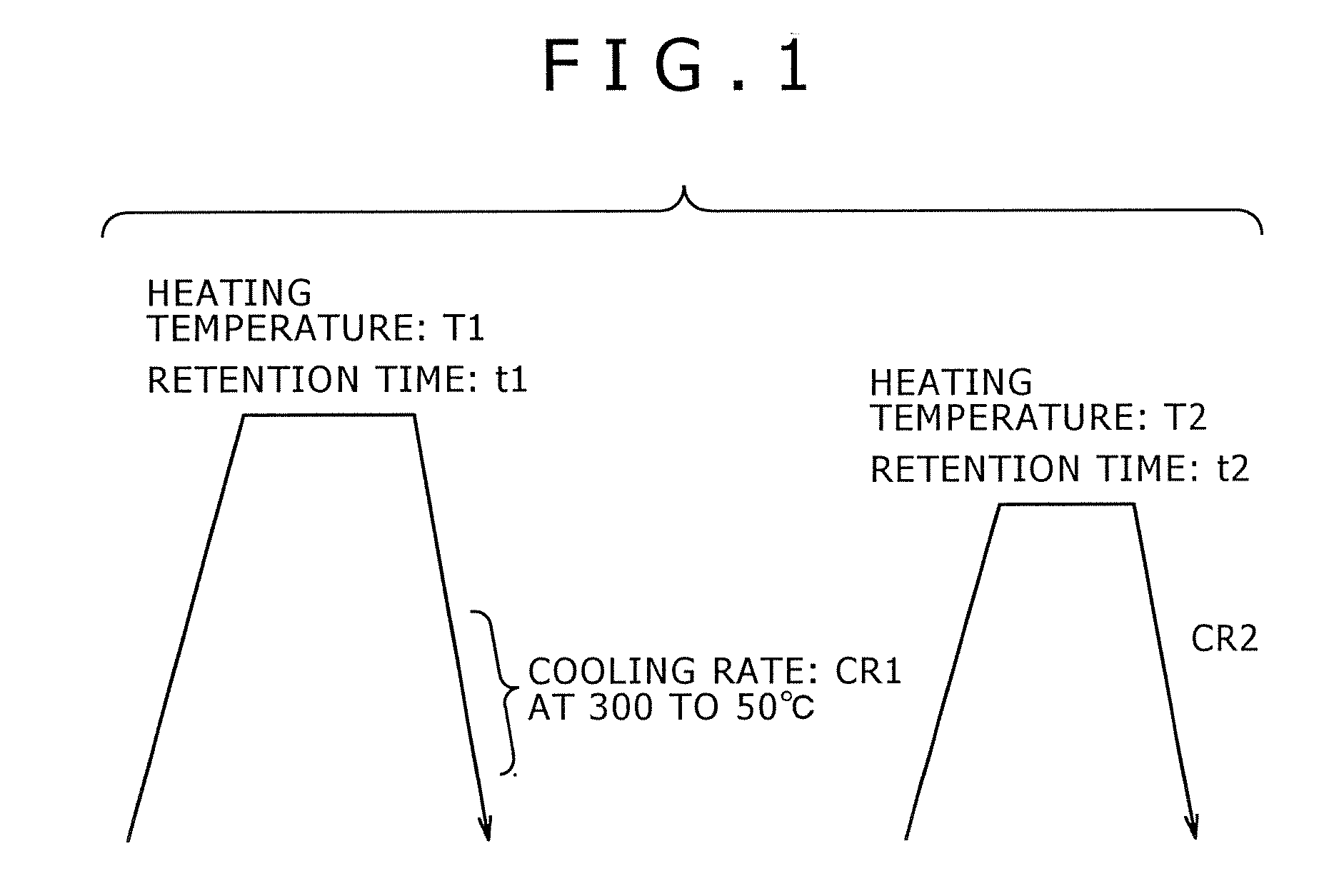
[0088] After forming Steel A1 to A33, with compositions listed in Table 1, from molten metal, steel rods of φ14 mm were obtained through hot rolling. Then, for evaluation of properties, each of the steel rod was cut to a length of 200 mm, followed by quenching and tempering under the conditions listed in Tables 2 and 3 (T1, t1, CR1, T2, t2, and CR2 in Tables 2 and 3 indicate marks of FIG. 1). Quenching and tempering were performed using the electric furnace, the salt furnace or the IH furnace.

[0089] In these examples, an average grain size of prior austenite was regulated by controlling a treatment condition for the quenching, and at the same time, the amount an...


PUM

PropertyMeasurementUnit
Grain sizeaaaaaaaaaa

Abstract

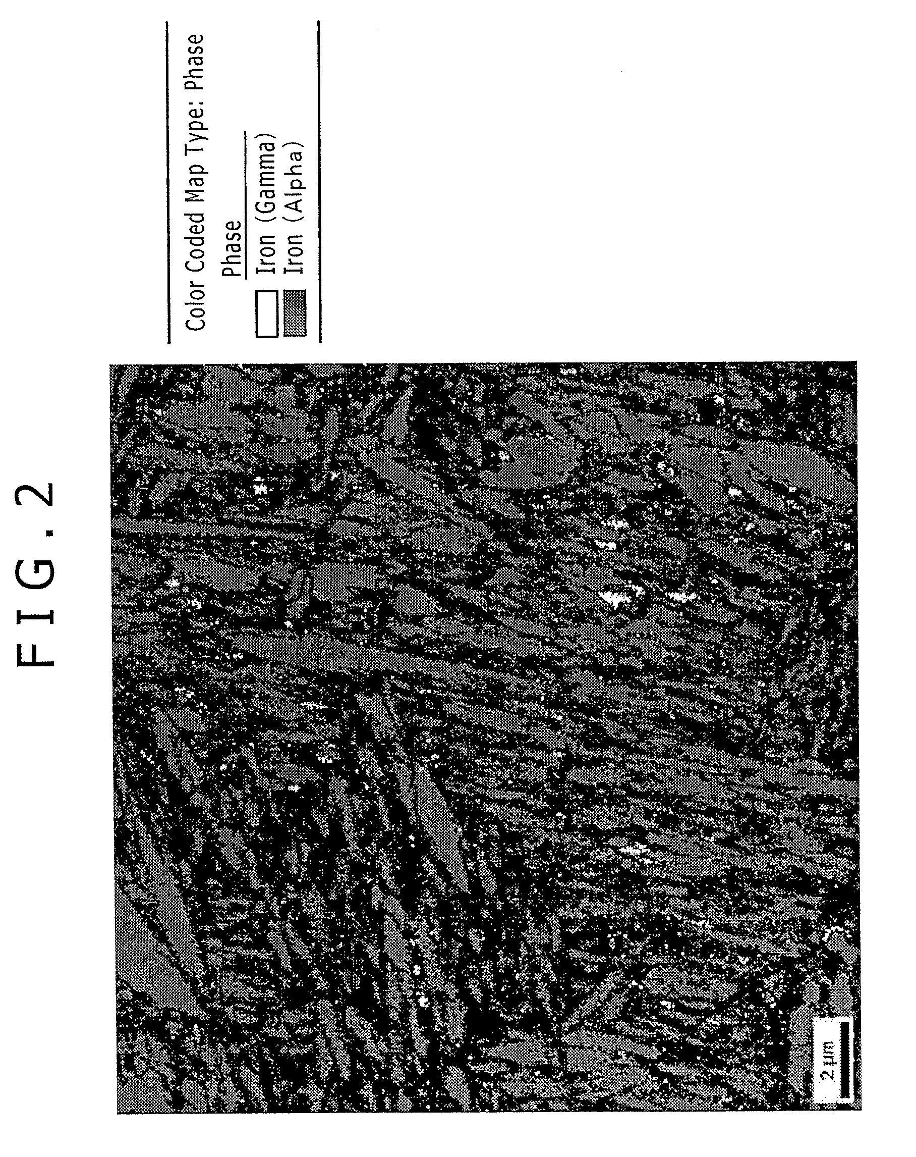
Disclosed herein is a high strength spring steel wire with excellent coiling properties and hydrogen embrittlement resistance. The steel wire comprises, by mass, 0.4 to 0.60% of C, 1.7 to 2.5% of Si, 0.1 to 0.4% of Mn, 0.5 to 2.0% of Cr, 0.015% or less of P (exceeding 0%), 0.015% or less of S (exceeding 0%), 0.006% or less of N (exceeding 0%), 0.001 to 0.07% of Al, and the remainder being Fe and unavoidable impurities. The steel wire has a structure wherein prior austenite has an average grain size of 12 μm or less, and retained austenite exists in an amount of 1.0 to 8.0 vol. % with respect to a whole structure of the steel wire. The retained austenite has an average grain size of 300 nm or less and a maximum grain size of 800 nm or less. The steel has a tensile strength of 1,900 MPa or more.

Description

BACKGROUND OF THE INVENTION [0001] 1. Field of the Invention [0002] The present invention relates to a high strength spring steel wire with excellent coiling properties and hydrogen embrittlement resistance, and more particularly, to a spring steel wire, which has enhanced coiling properties and hydrogen embrittlement resistance in a high strength range for a tensile strength of 1,900 MPa or more. [0003] 2. Description of the Related Art [0004] Requirement for weight reduction of an automotive vehicle is accompanied with reduction in size and thickness of vehicle components. In this regard, it is necessary for underbody components of the vehicle, such as a suspension spring and the like, to have high strength. However, since increase in strength of steel generally enhances atmospheric fatigue properties while reducing corrosion fatigue properties, it is difficult to improve both atmospheric fatigue properties and corrosion fatigue properties together with the strength of the steel. ...

Claims


Application Information

Patent Timeline
IPC IPC(8): C22C38/18
CPCC22C38/04C22C38/06C22C38/18C22C38/34C22C38/16C22C38/24C22C38/26C22C38/28C22C38/40
Inventor KOCHI, TAKUYAYAGUCHI, HIROSHI
Owner KOBE STEEL LTD
Learn More