Digital micro-mirror device assembly and optical projection system using the same

a micro-mirror device and optical projection technology, applied in the field of optical projection systems, can solve the problems of difficult to perform the positioning operation properly, difficult to replace the whole engine with a new one, and difficult to perform the positioning operation at locations not provided with positioning equipment, etc., to achieve the effect of facilitating the replacement of the circuit board, and improving the structure of the circuit board

Inactive Publication Date: 2007-06-07
SAMSUNG ELECTRONICS CO LTD
View PDF21 Cites 21 Cited by
  • Summary
  • Abstract
  • Description
  • Claims
  • Application Information

AI Technical Summary

Benefits of technology

[0018] Another aspect of the present invention is to provide a DMD assembly and an optical projection system using the same, in which the structure of the circuit board is improved to facilitate replacement of the circuit board.
[0019] Yet another aspect

Problems solved by technology

However, it is difficult to perform the positioning operation properly.
In particular, it is difficult to perform the positioning operation at locations not provid

Method used


Image

  • Digital micro-mirror device assembly and optical projection system using the same
  • Digital micro-mirror device assembly and optical projection system using the same
  • Digital micro-mirror device assembly and optical projection system using the same

Examples


Embodiment Construction

[0061] The matters defined in the description such as a detailed construction and elements are provided to assist in a comprehensive understanding of the embodiments of the invention. Accordingly, those of ordinary skill in the art will recognize that various changes and modifications of the embodiments described herein can be made without departing from the scope and spirit of the invention. Also, descriptions of well-known functions and constructions are omitted for clarity and conciseness.

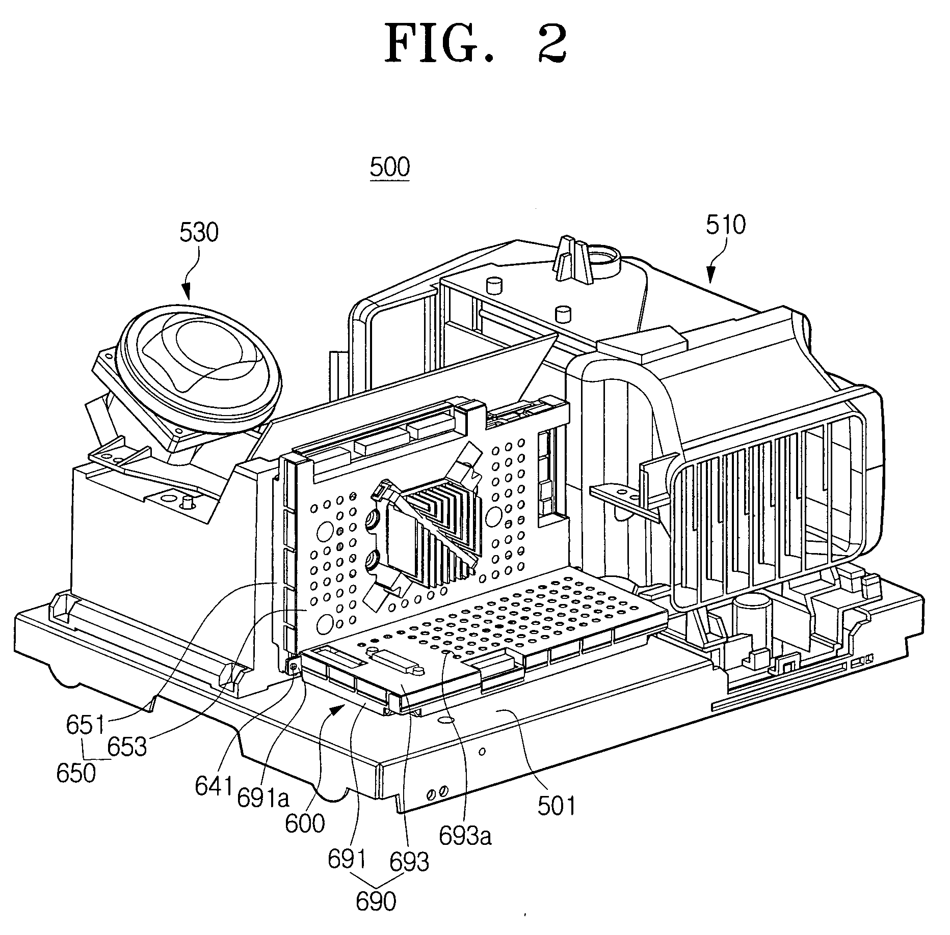
[0062]FIG. 2 is a perspective view of an optical projection system according to one embodiment of the present invention.

[0063] Referring to FIG. 2, the optical projection system 500 includes a base 501, a lamp 510, a DMD assembly 600, and a projection lens 530. The light emitted from the lamp 510 is reflected toward the projection lens 530 by a DMD of the DMD assembly 600, and the reflected light is projected onto a projection surface of a screen (not shown).

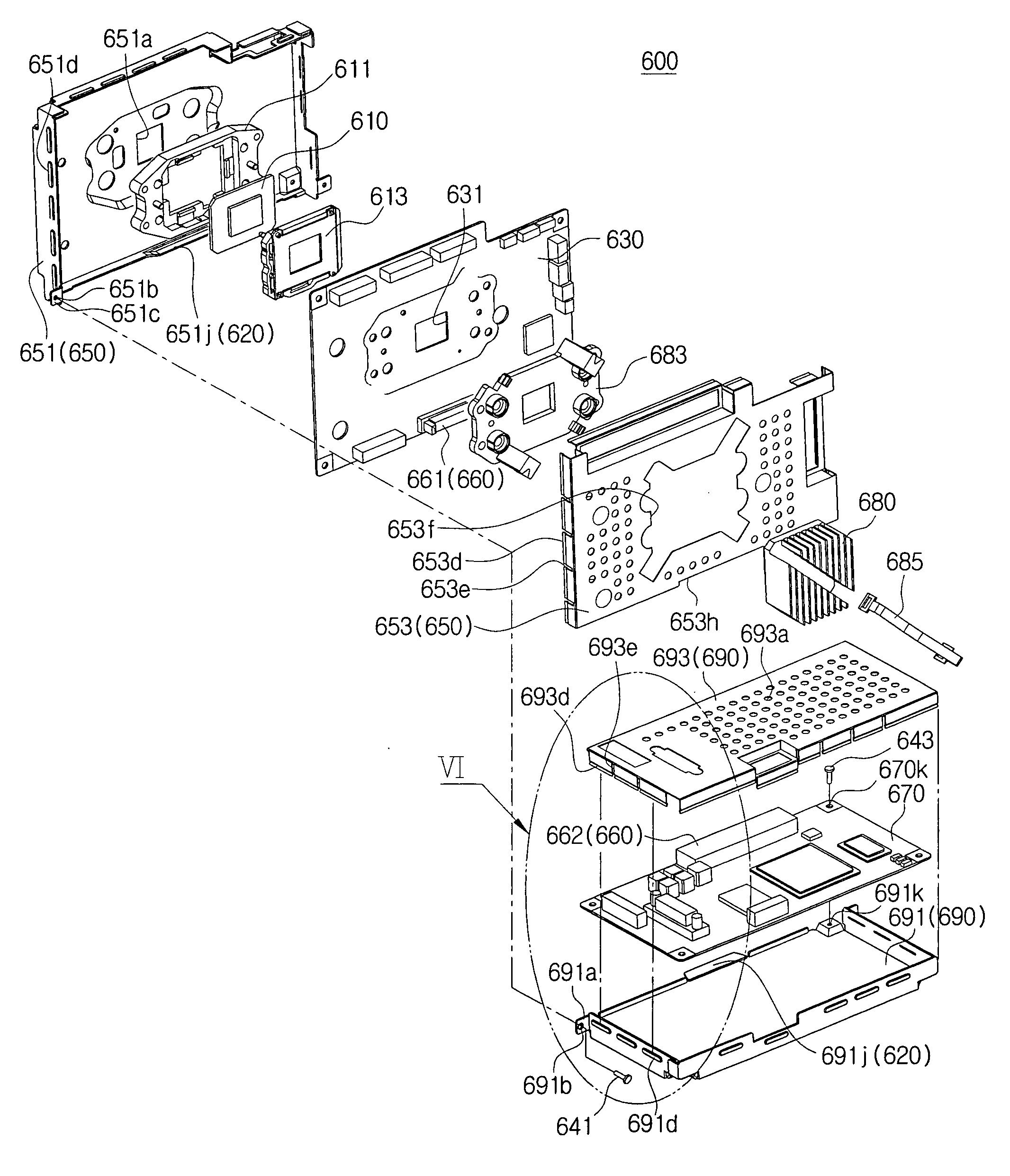
[0064]FIG. 3 is an enlarged perspe...


PUM


Abstract

An optical projection system is disclosed. The optical projection system includes a base, a lamp provided in the base, a DMD assembly provided at one side of the lamp to generate image light from light irradiated by the lamp, and a projection unit for projecting the image light formed through the DMD assembly. The DMD assembly includes a DMD, a main circuit board provided with the DMD at one side, and a side circuit board which may be detached from or fixed to the main circuit board independently from the DMD assembly. The side circuit board may be provided at one side of the main circuit board at a right angle.

Description

CROSS-REFERENCE TO RELATED APPLICATIONS [0001] This application claims the benefit under 35 U.S.C. § 119(a) of Korean Patent Application No. 2005-117719, filed on Dec. 5, 2005, the entire content of which is hereby incorporated by reference. BACKGROUND OF THE INVENTION [0002] 1. Field of the Invention [0003] The present invention relates to an optical projection system. More particularly, the present invention relates to an optical projection system having an improved circuit board structure. [0004] 1. Description of the Related Art [0005] An optical projection system projects a small sized image onto a large screen using an optical means. Typical types of optical projection systems include cathode ray tube (CRT) projection systems, liquid crystal display (LCD) projection systems, and digital light processing (DLP) projection systems. [0006] CRT projection systems are the oldest and form an image on a screen by reflecting a small sized CRT with a mirror. LCD projection systems trans...

Claims


Application Information

Patent Timeline
IPC IPC(8): G03B21/28G03B21/22G03B21/14
CPCG03B21/00G03B21/14H05K1/14G03B21/008G03B33/12G03B21/005H04N5/74
Inventor KANG, BYUNG-JO
Owner SAMSUNG ELECTRONICS CO LTD
Why Eureka
Try Eureka