Interference measurement system self-alignment method

a self-alignment and measurement system technology, applied in the direction of measuring devices, instruments, using optical means, etc., can solve the problems of reducing the applicability of the industry, reducing so as to prolong the measurement duration, increase the accuracy of the measurement of objects, and increase the measurement rang

Inactive Publication Date: 2007-06-07
CHROMA ATE
View PDF3 Cites 54 Cited by
  • Summary
  • Abstract
  • Description
  • Claims
  • Application Information

AI Technical Summary

Benefits of technology

[0009] Therefore, the objective of the present invention is to provide a self-alignment method used in an interference measurement system, which is utilized to replace the conventional inclination angle manual adjustment method, wherein the direction and spacings of the interference fringes of the image of the object are used to determi...

Problems solved by technology

Moreover, the time required for the measurement also increases correspondingly, thus reducing its applicability in the industry significantly.
As such, the inclusion of too much undesirable noise would adversely affect the accuracy in determining the central position of the wave packets, thus resulting in the deviation of the central position and the increase of measurement errors of the interference measurement system.
In view of the afore-mentioned analyses, it is evident that the inclination angle of the object to be measured could have en...

Method used


Image

  • Interference measurement system self-alignment method
  • Interference measurement system self-alignment method
  • Interference measurement system self-alignment method

Examples


Embodiment Construction

[0021] The purpose, construction, features, and functions of the present invention can be appreciated and understood more thoroughly through the following detailed description with reference to the attached drawings.

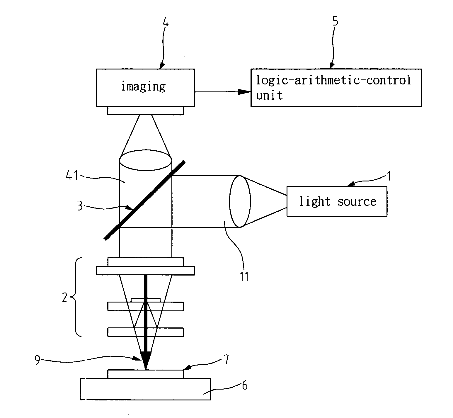
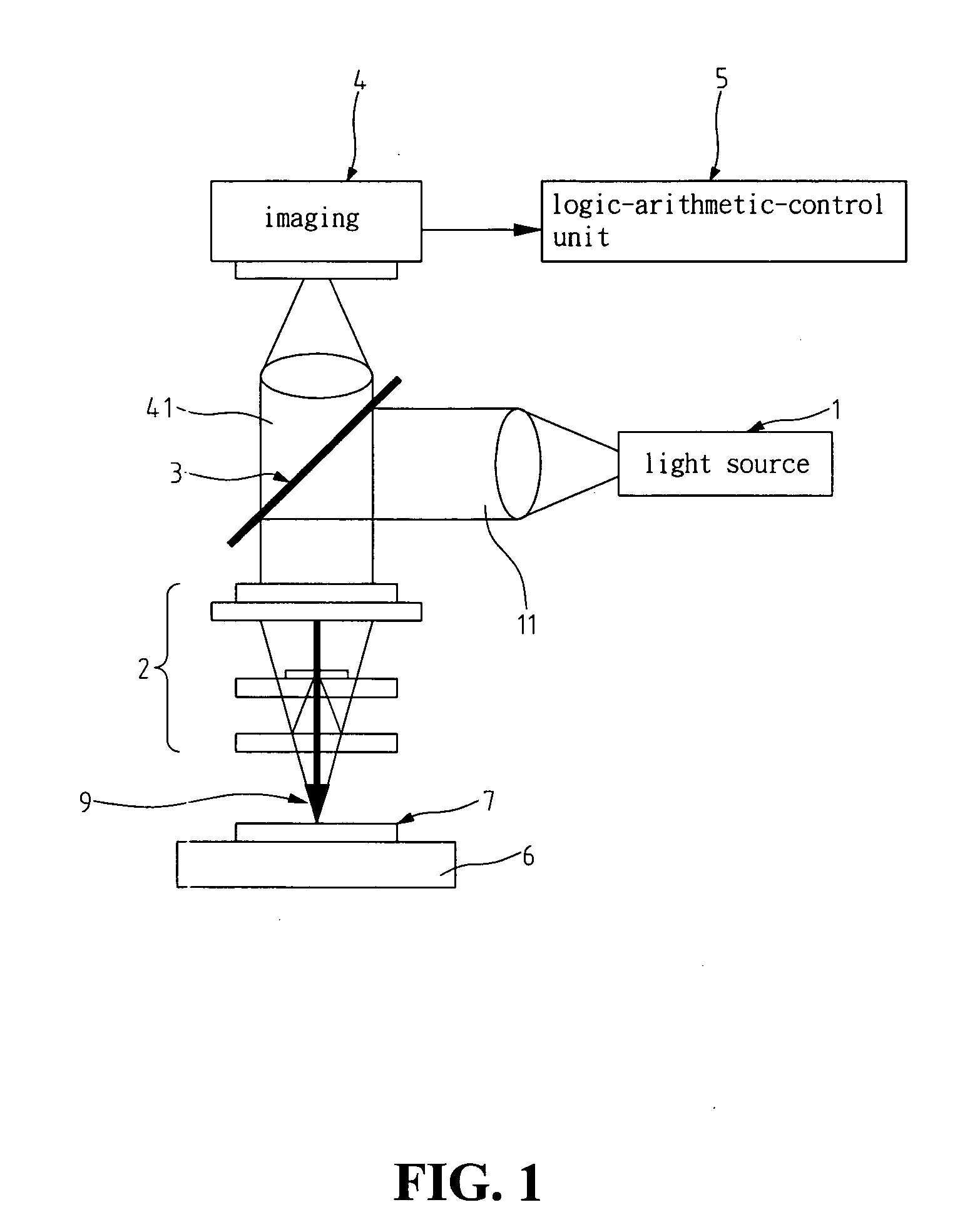
[0022] Firstly, referring to FIG. 1 for a schematic diagram of the an interference measurement system utilized in the self-alignment method according to an embodiment of the present invention. As shown in FIG. 1, the interference measurement system of the present invention includes: a light source 1, a set of object lenses 2, a light beam guidance device 3, an imaging system 4, a logic-arithmetic-control unit 5, and an object platform 6. Wherein the light source 1 is used to generate incident light beam 11 of white light signal; the set of object lenses 2 is composed of an interference object lens and a focal length adjustment means; the light beam guidance device 3 is an optical device, which is used to guide the light signal emitted from the light source of the system...


PUM


Abstract

An interference measurement system self-alignment method, which can be realized through an optical image interference measurement system. The method comprises the following steps of: utilizing the imaging device to get the optical information of the object to be measured and store the optical information thus obtained; performing the inclination adjustment of the first direction rotation axis of the object platform based on the direction of the interference fringe in the optical information until the interference fringes are adjusted to a defined orthogonal direction, thus eliminating the inclination of the first direction rotation axis; and performing the inclination adjustment of the second direction rotation axis of the object platform based on the expansion direction of the interference fringe in the optical information until the spacing of the interference fringes are adjusted to the maximum, thus eliminating the inclination of the second direction rotation axis.

Description

BACKGROUND OF THE INVENTION [0001] 1. Field of the Invention [0002] The present invention relates to a self-alignment method used in an interference measurement system, and in particular to a self-alignment method used in an imaging device, so that the inclination angle between the optical axis of an imaging device and an object to be measured can be eliminated or at least reduced significantly, so as to improve the accuracy of measurement and the effectiveness of the imaging device. [0003] 2. The Prior Arts [0004] In general, an interference measurement system, and in particular, a white light interference measurement system is used to measure the surface profile of a micro-structure. To increase the accuracy of measurement and the effectiveness of the white light interference measurement system, the effect of inclination angle of the object to be measured relative to the interference system must be considered. Usually, in the implementation of this kind of measurement technology, ...

Claims


Application Information

Patent Timeline
IPC IPC(8): G01B11/02
CPCG01B11/2441
Inventor LIAO, CHIEN-CHONGLIN, YAO-MINCHANG, HUANG-CHANGCHANG, WEI-CHE
Owner CHROMA ATE
Why Eureka
Try Eureka