Supercharge Your Innovation With Domain-Expert AI Agents!

Laser control

Inactive Publication Date: 2007-06-07
BOOKHAM TECH
View PDF9 Cites 10 Cited by
  • Summary
  • Abstract
  • Description
  • Claims
  • Application Information

AI Technical Summary

Benefits of technology

[0010] It is an aim of the present invention to provide a new type of laser control technique, which utilises the existing laser control hardware, but can compensate for variations in the reference voltage with a view to more accurately controlling one or more output characteristics of the laser such as, for example, the average laser power and / or extinction ratio.
[0011] According to a first aspect of the present invention, there is provided amethod of operating a laser using a laser driver, including the steps of: providing the laser driver with a first electrical input indicative of a desired value for an output characteristic of the laser; and controlling a second electrical input from the laser driver to the laser on the basis of said first electrical input with reference to a first electrical reference; and further including the step of: controlling the first electrical input on the basis of an electrical indicator of an actual value of said output characteristic of the laser with reference to a second electrical reference of greater reliability than the first electrical reference so as to compensate for any variation of the first electrical reference.
[0018] According to a second aspect of the present invention, there is provided a control system for operating a laser, including: a laser driver; a controller for providing the laser driver with a first electrical input indicative of a desired value for an output characteristic of the laser;, wherein the laser driver is arranged to control a second electrical input from the laser driver to the laser on the basis of said first electrical input with reference to a first electric reference; and wherein the controller is arranged to control the first electrical input on the basis of an electrical indicator of an actual value of said output characteristic of the laser with reference to a second electrical reference of greater reliability than the first electrical reference so as to compensate for any variations of the first electrical reference.
[0032] According to a third aspect of the present invention, there is provided a controller for controlling a laser driver for operating a laser, wherein said controller is arranged to provide the laser driver with a first electrical input indicative of a desired value for an output characteristic of the laser; on the basis of which the laser driver controls a second electrical input from the laser driver to the laser with reference to a first electric reference; wherein the controller is arranged to control the first electrical input on the basis of an electrical indicator of an actual value of said output characteristic of the laser with reference to a second electrical reference of greater reliability than the first electrical reference so as to compensate for any variations of the first electrical reference.

Problems solved by technology

It has been observed that there can be a problem with this conventional approach.

Method used


Image

  • Laser control
  • Laser control
  • Laser control

Examples


Embodiment Construction

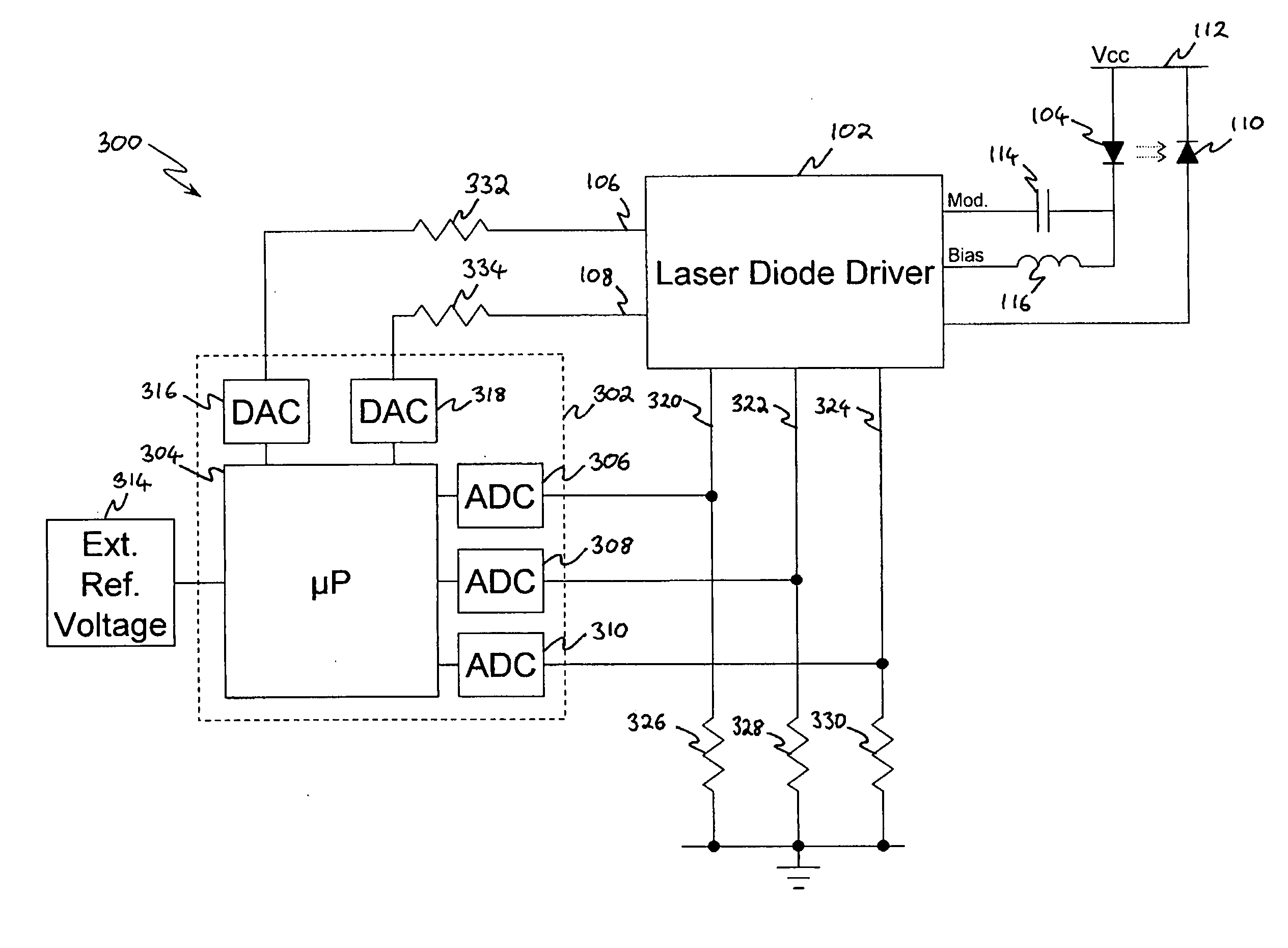
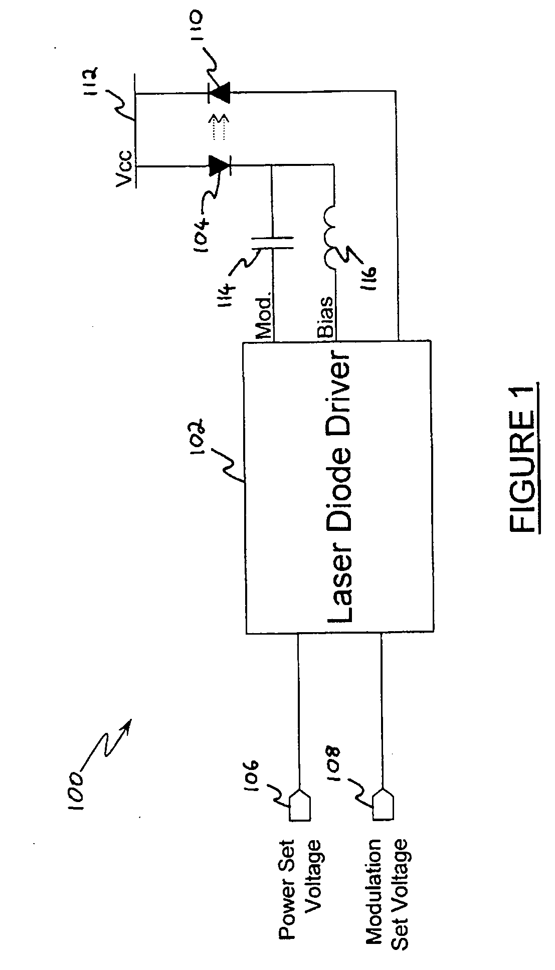
[0043] Reference will first be made to FIG. 3, in which is shown a laser control system 300 according to an embodiment of the present invention. The laser control system 300 comprises the same laser diode driver 102, as shown in FIG. 1, driving the laser diode 104 and receiving feedback from the monitor photodiode 110. As described previously, the laser diode driver 102 is controlled with a power set input 106 and a modulation set input 108.

[0044] The laser control system 300 in FIG. 3 also comprises a controller 302. The controller reads parameters of the laser diode operation and provides the inputs to the laser diode driver 102 in order to compensate for inaccuracies in the laser diode driver 102, such as the internal voltage reference.

[0045] The controller 302 comprises a microprocessor 304, which controls the operation of the controller 304. The controller also comprises several analogue to digital converters (ADC) (306, 308, 310) for providing measurements of input voltages ...


PUM


Abstract

A control system for operating a laser, including: a laser driver and a controller for providing the laser driver with a first electrical input indicative of a desired value for an output characteristic of the laser. The laser driver is arranged to control a second electrical input from the laser driver to the laser on the basis of the first electrical input with reference to a first electric reference. The controller is arranged to control the first electrical input on the basis of an electrical indicator of an actual value of the output characteristic of the laser with reference to a second electrical reference of greater reliability than the first electrical reference, so as to compensate for any variations of the first electrical reference.

Description

FIELD OF THE INVENTION [0001] The present invention relates to a laser control method and system. BACKGROUND OF THE INVENTION [0002] Laser diodes are widely used for optical communications. In order to utilise a laser diode to produce communications signals, it is driven with certain electrical signals. In particular, the laser diode is provided with biasing and modulation currents superimposed on each other. These currents can be generated by a laser diode driver system. [0003] A known laser control system 100 is shown in FIG. 1. The control system comprises a laser diode driver 102, which is connected to a laser diode 104. The laser diode driver 102 has a power set voltage input 106 and a modulation set voltage input 108, which control the operation of the laser diode driver 102. A monitor photodiode 110 is also connected to the laser diode driver 102. Both the laser diode 104 and monitor photodiode are connected to a voltage supply 112. The laser diode driver provides driving sig...

Claims


Application Information

Patent Timeline
IPC IPC(8): H01S3/13H01S3/00
CPCH01S5/02415H01S5/0427H01S5/06832
Inventor PAN, QIBARNARD, JOSEPH
Owner BOOKHAM TECH
Features
  • R&D
  • Intellectual Property
  • Life Sciences
  • Materials
  • Tech Scout
  • Unparalleled Data Quality
  • Higher Quality Content
  • 60% Fewer Hallucinations
Learn More