
Method of Modifying a Turbocompressor

a turbocompressor and compressor technology, applied in the direction of machines/engines, engine starters, liquid fuel engines, etc., can solve the problems of not being able to deliver the entire quantity of volumetric inlet flow, the volumetric flow in the rear compressor stages turns out to be markedly smaller, and the pressure build-up in the front compressor stages is further increased. , to achieve the effect of increasing the nominal mass flow

Inactive Publication Date: 2007-06-07
ANSALDO ENERGIA IP UK LTD
View PDF3 Cites 3 Cited by
  • Summary
  • Abstract
  • Description
  • Claims
  • Application Information

AI Technical Summary

Benefits of technology

[0007] One of numerous aspects of the present invention involves a method of the aforementioned type, and can include a modified compressor which has an increased nominal mass flow can be started up without any problems.
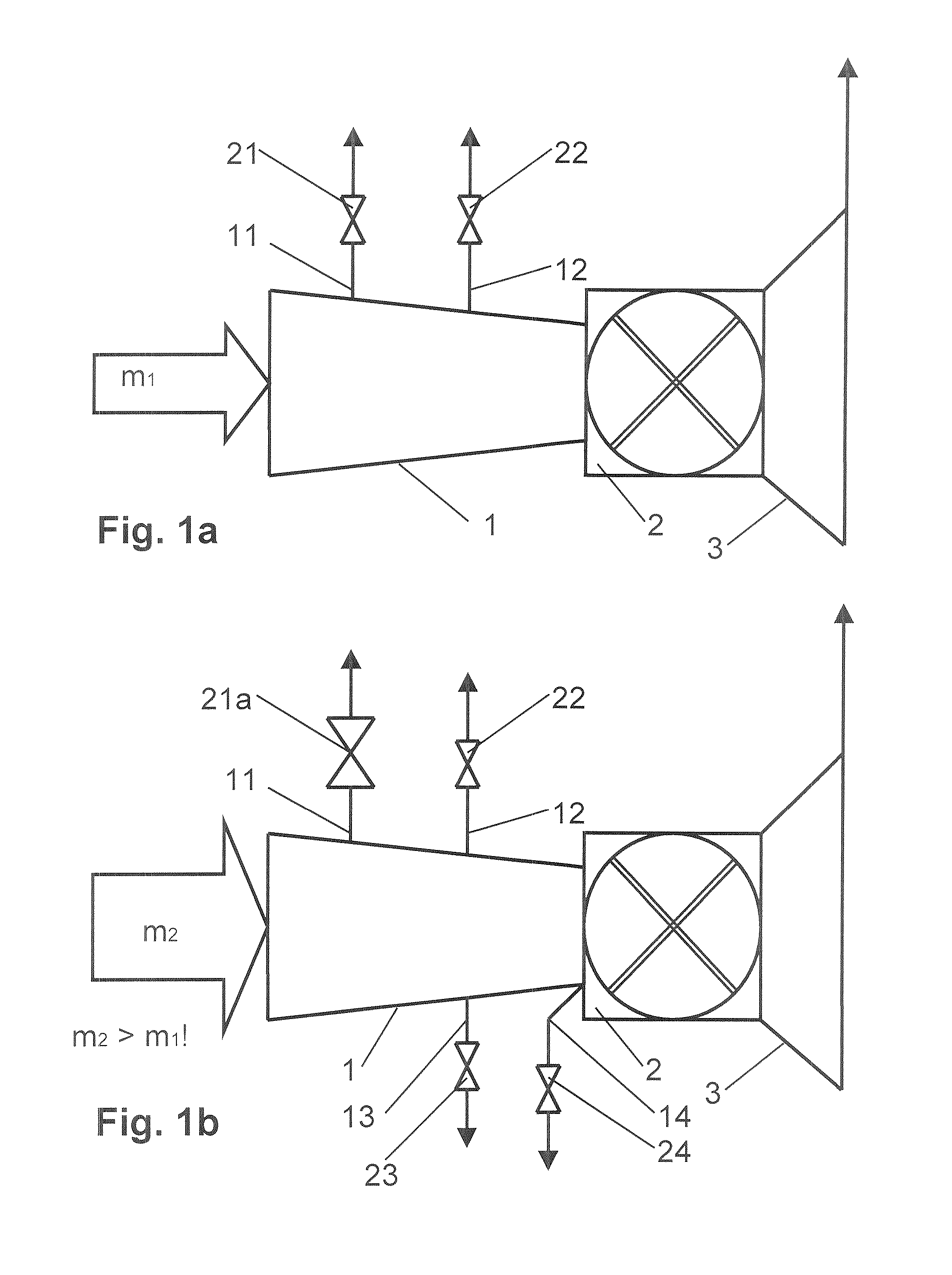
[0008] According another aspect of the present invention, the capacity for blowing off compressed or partly compressed fluid can be increased. The capacity is increased, for example, in the same ratio as the volumetric intake flow is increased by the modification of the compressor blades. According to a first exemplary embodiment of the invention, the blow-off capacity is increased by increasing the critical cross section of flow of at least one blow-off line connected to the compressor. In general, the narrowest cross section of the flow line must be increased in this case. The narrowest cross section is often present in the shut-off member which serves to close and open up the blow-off line. The invention can therefore be realized in a very simple manner by the shut-off member, also called a shut-off valve, being replaced by a shut-off member having an enlarged free cross section.
[0010] Blow-off lines are in general arranged on the compressor in such a way that partly compressed fluid is blown off. For example, the blow-off line branches off between two compressor stages. This ensures that, as mentioned above, when the blow-off line is opened, the mass flow in the front compressor stages is greater than in the rear compressor stages. Furthermore, in one embodiment, if the compressor is connected to a load for compressed fluid, the compressor being arranged upstream of the load, for example a turbine, a blow-off line can be arranged downstream of the compressor and upstream of the load. For example, a blow-off line of a compressor of a gas turboset is arranged downstream of the compressor and upstream of a first combustion chamber of the gas turboset. During the start-up of the compressor, the back pressure against which the compressor has to work is reduced and thus the risk of separation is decreased by opening a blow-off line arranged in such a way.

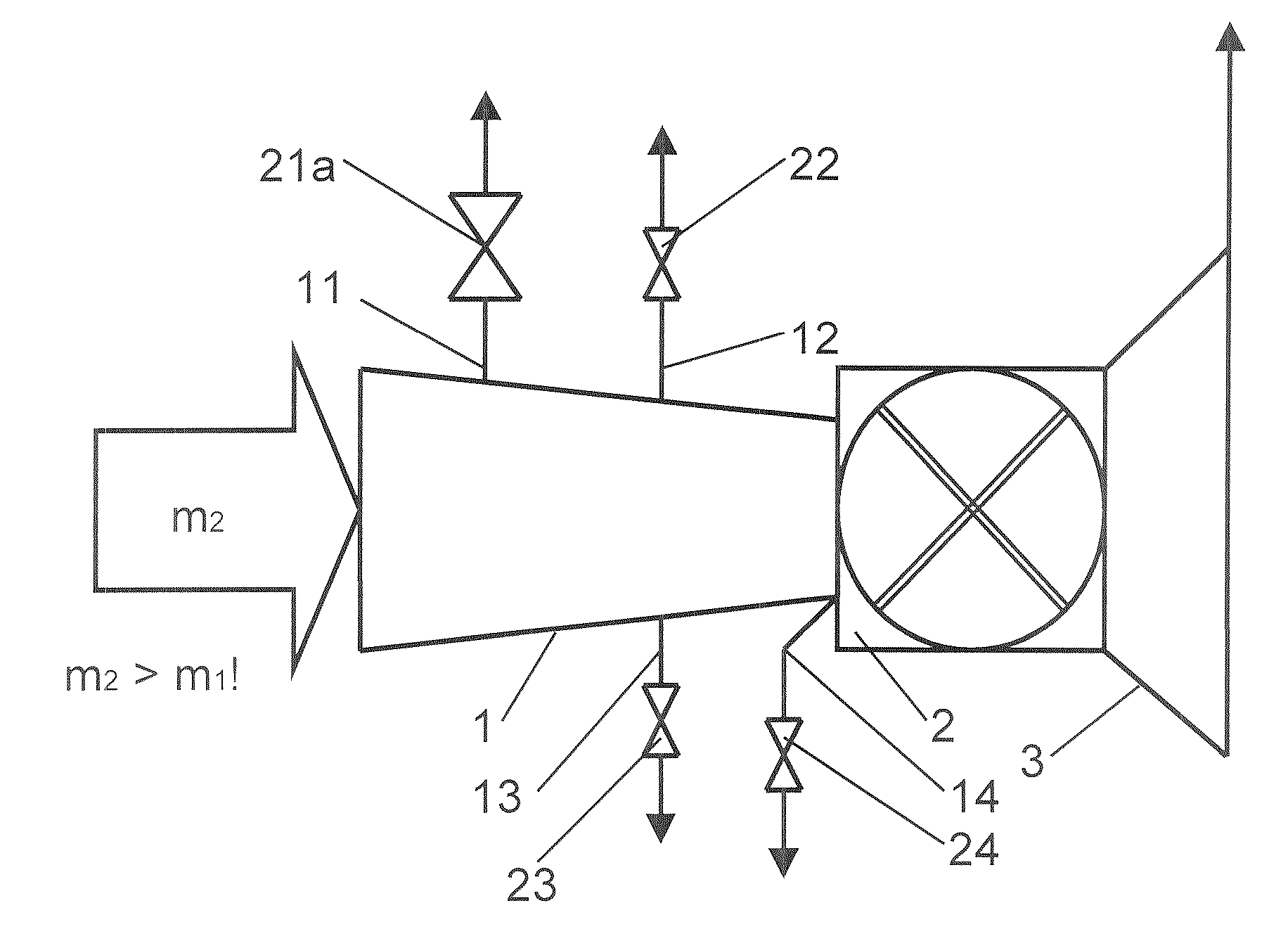
Problems solved by technology

During the start-up of a turbocompressor, the compressor, on account of the stage kinematics at low speed, is not able to deliver the entire delivery quantity of the volumetric inlet flow against the pressure imposed by the load.
It is also problematical at underspeed of a turbocompressor that the volumetric flow in the rear compressor stages turns out to be markedly smaller than corresponds to the design of the cross sections of flow.
On the other hand, obstruction of the cross sections of flow potentially occurs in the rear compressor stages, which further increases the pressure build-up in the front compressor stages.

Method used


Image

  • Method of Modifying a Turbocompressor
  • Method of Modifying a Turbocompressor

Examples


Embodiment Construction

[0015]FIG. 1a shows a gas turboset, including a compressor 1, a combustion chamber 2, and a turbine 3, as is readily familiar to the person skilled in the art. During operation of the gas turboset, the compressor 1 draws in a volumetric intake flow or a nominal mass flow ml. This air mass flow is compressed in the compressor 1. A fuel mass flow is burned in the compressed combustion air in the combustion chamber 2, and the hot flue gas produced is expanded in the turbine 3 to perform work. Blow-off lines 11 and 12 with shut-off members 21 and 22 are arranged at the compressor 1. As explained at the beginning, these blow-off lines serve to blow off partly compressed air from the compressor during start-up of the compressor at speeds markedly below the rated speed.

[0016] The gas turboset after a modification according to the invention of the compressor 1 is shown in FIG. 1b. Due to the provision of improved compressor blades, the volumetric intake flow of the compressor 1 increases, ...


PUM


Abstract

In a method of modifying a turbocompressor, the compressor blades are replaced by new compressor blades in such a way that the delivered mass flow of the compressor increases. At the same time, the capacities for blowing off during the start-up are increased.

Description

[0001] This application is a Continuation of, and claims priority under 35 U.S.C. § 120 to, International application number PCT / EP2005 / 053378, filed 14 Jul. 2005, and claims priority under 35 U.S.C. § 119 therethrough to German application number 10 2004 036 238.6, filed 26 Jul. 2004, the entireties of which are incorporated by reference herein.BACKGROUND OF THE INVENTION [0002] 1. Field of the Invention [0003] The invention relates to a method of modifying a turbocompressor, to a turbocompressor modified according to this method, and to the use of the turbocompressor so modified. [0004] 2. Brief Description of the Related Art [0005] During the start-up of a turbocompressor, the compressor, on account of the stage kinematics at low speed, is not able to deliver the entire delivery quantity of the volumetric inlet flow against the pressure imposed by the load. It is also problematical at underspeed of a turbocompressor that the volumetric flow in the rear compressor stages turns out...

Claims


Application Information

Patent Timeline
Patent Type & Authority Applications(United States)
IPC IPC(8): F01D25/00
CPCF04D27/02F04D29/321Y10S415/912F04D29/32
Inventor GLESTI, DANIELMICHELI, MARCOPALKOVICH, THOMASRICK, WIFRIEDSAVIC, SASHA
Owner ANSALDO ENERGIA IP UK LTD
Learn More