Distributed cell balancing

a cell and cell technology, applied in the direction of electrical equipment, network planning, wireless commuication services, etc., can solve the problems of excessive load on the radio resources of the cell, poor service quality, limited capacity, etc., to prevent hot-spot type overload and efficient load balancing.

Inactive Publication Date: 2007-06-07
CELLETRA
View PDF8 Cites 130 Cited by
  • Summary
  • Abstract
  • Description
  • Claims
  • Application Information

AI Technical Summary

Benefits of technology

[0018] The present invention describes a load sharing mechanism for sector based cellular base stations for preventing hot-spot type overload from overwhelming a given sector on a base station. In one embodiment loads in hot-spots in one sector are switched over to be served by sectors which are less loaded. The hotspots are covered by repeaters or like relay devices and load sharing is achieved by reassigning the repeaters to different sectors. Where the principle cause of overload is changes within the hotspots then reassigning the repeaters is a more efficient way of load balancing than traditional changing of the antenna patterns or shaping the sectors or the cell. A system according to the present embodiments can be applied to an existing base station that does not require any modification to the baseband part of the base station, and a preferred embodiment uses the existing base station antennas for communicating with the repeaters.

Problems solved by technology

A coverage problem might arise due to “radio holes”, that is regions within the cell / sector which suffer large propagation losses due to uneven topography or buildings, impairing the quality of service.
Another problem which might arise is “hot spots”, where a large concentration of users, usually not in the vicinity of the base station, causes an excessive load on the cell's radio resources.
This is especially relevant to CDMA systems, where the capacity is interference limited.
However, while each sector might be optimized with regards to its own resource allocation, different sectors within the cell may at times be heavily loaded, requiring additional capacity, while other sectors might be lightly loaded, thus having spare capacity.
This load imbalance between the sectors could be the result of non-optimal network design, or due to changes in communication patterns since the cellular system was originally installed.

Method used


Image

  • Distributed cell balancing
  • Distributed cell balancing
  • Distributed cell balancing

Examples


Embodiment Construction

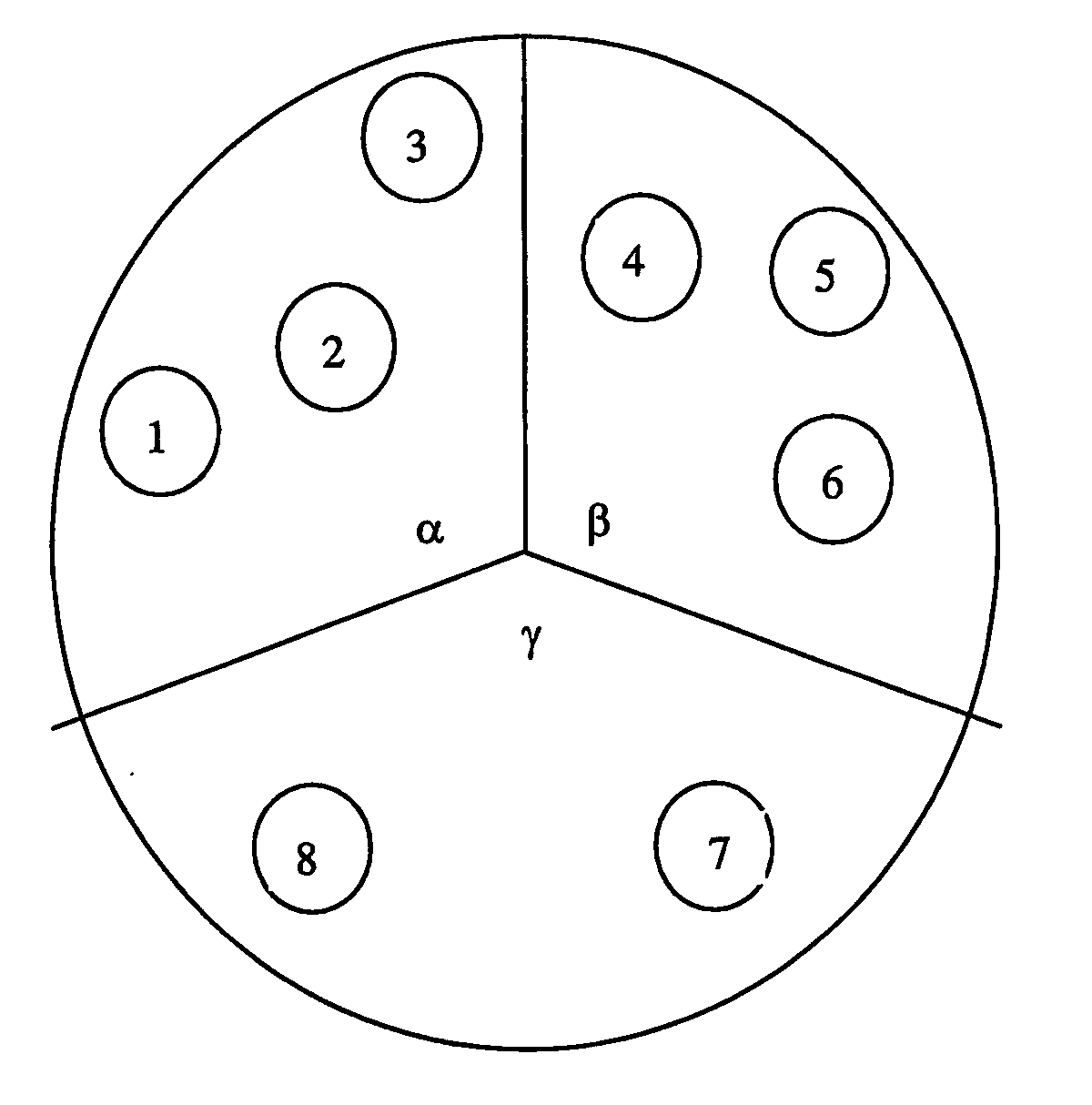
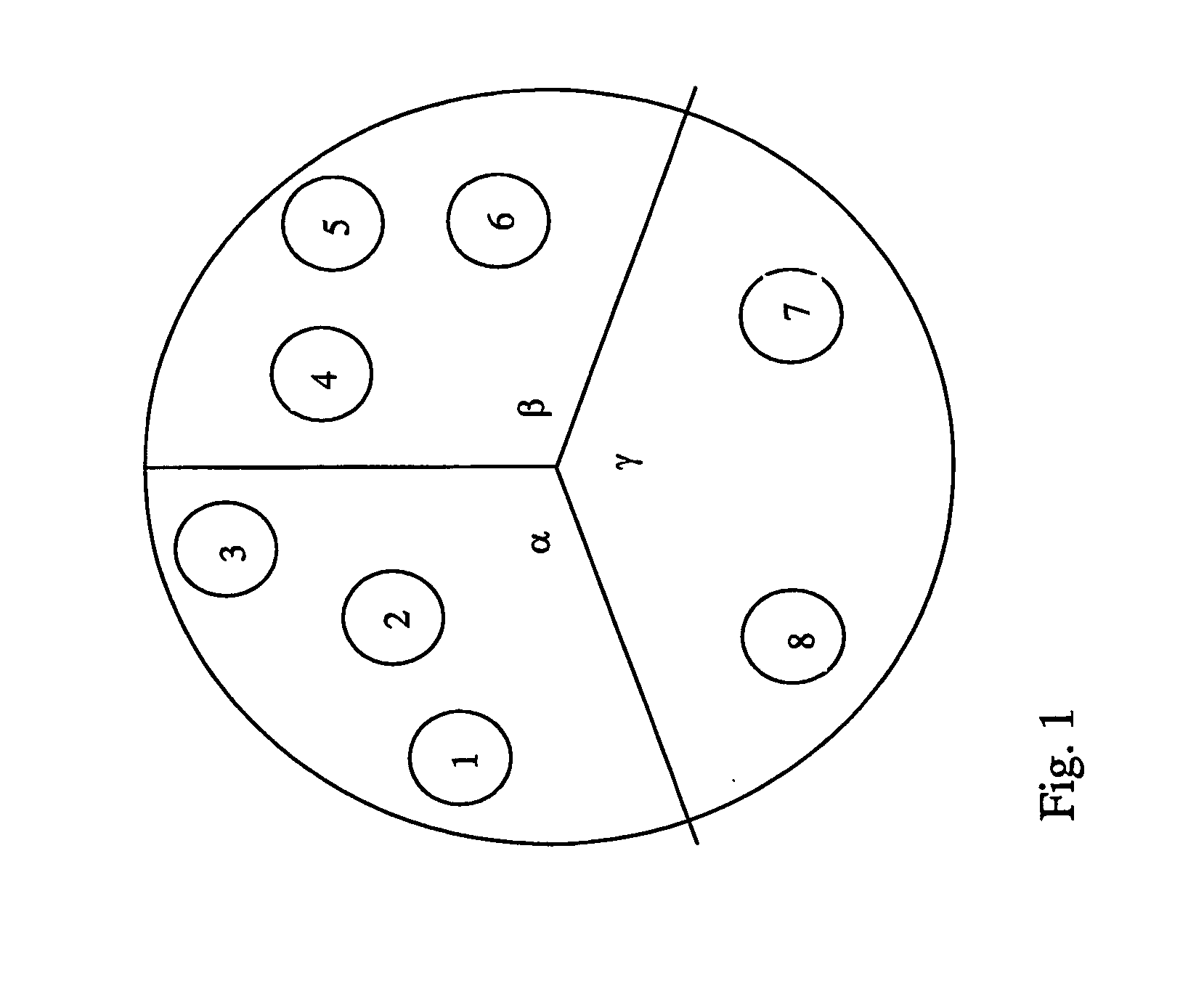
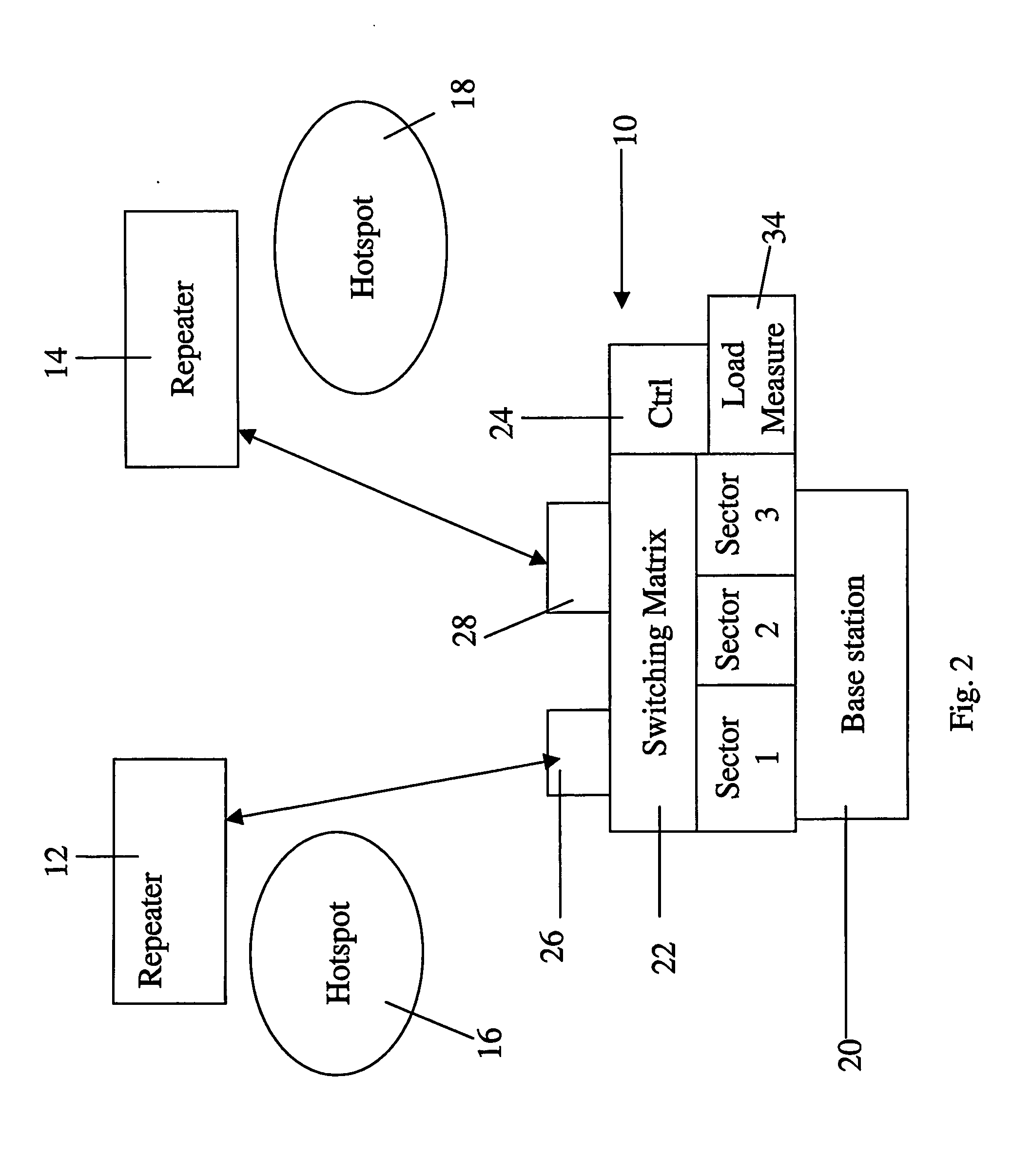
[0093] In the present embodiments we consider a sectored cell, where hot-spots in each sector are local, each served by its own repeater, and may draw high capacity at different times. Load sharing is applied between sectors by connecting repeaters which are located in one sector (the loaded sector) to other sectors which are less loaded. This is accomplished by connecting the repeater to the donor sector base station using frequency F2. The repeater converts the transmission back to F1, the original frequency of the donor base station. Softer handoff is applied between the repeaters and the sectors in which they are located.

[0094] Load balancing is performed and maintained by using a control subsystem, which measures the load in each sector, as well as the load served by each repeater, and an optimization algorithm, which dynamically assigns repeaters to sectored base stations, using a switching matrix.

[0095] The principles and operation of a load balancing system according to th...


PUM


Abstract

A load balancing system for dynamic balancing of load between sectors of a sectored cellular base station, comprises a plurality of repeaters with local coverage in the sectors, and a switching matrix, for associating between the repeaters and the base station, and for allowing the repeaters to be switched between different sectors. If the system uses the base station assigned frequency band for communication with the repeaters then the system can be provided with minimal interference as an add-on to a legacy base station. An add-on may also be provided using microwave frequency and dedicated antennas.

Description

FIELD AND BACKGROUND OF THE INVENTION [0001] The present invention relates to load balancing within cells in cellular telephony systems and, more particularly, but not exclusively to a system for dynamically balancing load traffic between sectors in given cells. [0002] Conventional cellular networks employ an architecture which divides a geographical area into coverage areas, called cells, and a base station is placed at the center of the cell to serve the cellular traffic within the cell. [0003] To increase the capacity (the total data or the total number of users served) the cell is further divided into sectors (typically 3 sectors), which are served from the same base location, using dedicated baseband resources, transceivers and directional antennas, per sector. [0004] A coverage problem might arise due to “radio holes”, that is regions within the cell / sector which suffer large propagation losses due to uneven topography or buildings, impairing the quality of service. This effec...

Claims


Application Information

Patent Timeline
Patent Type & Authority Applications(United States)
IPC IPC(8): H04Q7/20H01QH04W16/06H04W16/24
CPCH04W16/06H04W16/24
Inventor SHAPIRA, JOSEPH
Owner CELLETRA
Why Eureka
Try Eureka