
Systems and methods for implementing CORDIC rotations for projectors and related operators

a projector and projector technology, applied in the field of wireless communication, can solve the problems of inter-cell interference, intra-cell interference between signals, inter-channel interference, etc., and achieve the effect of reducing memory demands and eliminating memory altogether

Active Publication Date: 2007-06-07
III HLDG 1
View PDF14 Cites 13 Cited by
  • Summary
  • Abstract
  • Description
  • Claims
  • Application Information

AI Technical Summary

Benefits of technology

[0011] In another aspect, CORDIC used to implement orthogonal projections can comprise a single pipeline pair machine for implementing the projections. The pipeline output data can be re-circulated in order to minimize demands on memory.
[0015] In still another embodiment, hierarchical coordinate pairing can be used to limit computational noise due to chained computations used in the CORDIC rotation.

Problems solved by technology

Inter-channel interference occurs when multiple base stations communicating over the same frequency band interfere with each other.
Intra-cell interference occurs when communication devices within a cell all communicate with the base station over the same carrier-frequency band and a common pseudo-noise carrier.
However, channel effects within the cell can degrade the orthogonal relationship between the coded signals, causing intra-cell interference between signals destined for different communication devices.
In addition, signals from adjacent cells can also cause interference.
Thus, inter-cell interference may result from communication signals in an adjacent cell, such as transmissions originating near the edge of the adjacent cell.
However, this trade-off is often tolerable for many implementations.

Method used


Image

  • Systems and methods for implementing CORDIC rotations for projectors and related operators
  • Systems and methods for implementing CORDIC rotations for projectors and related operators
  • Systems and methods for implementing CORDIC rotations for projectors and related operators

Examples


Embodiment Construction

.”

BRIEF DESCRIPTION OF THE DRAWINGS

[0024] Features, aspects, and embodiments of the inventions are described in conjunction with the attached drawings, in which:

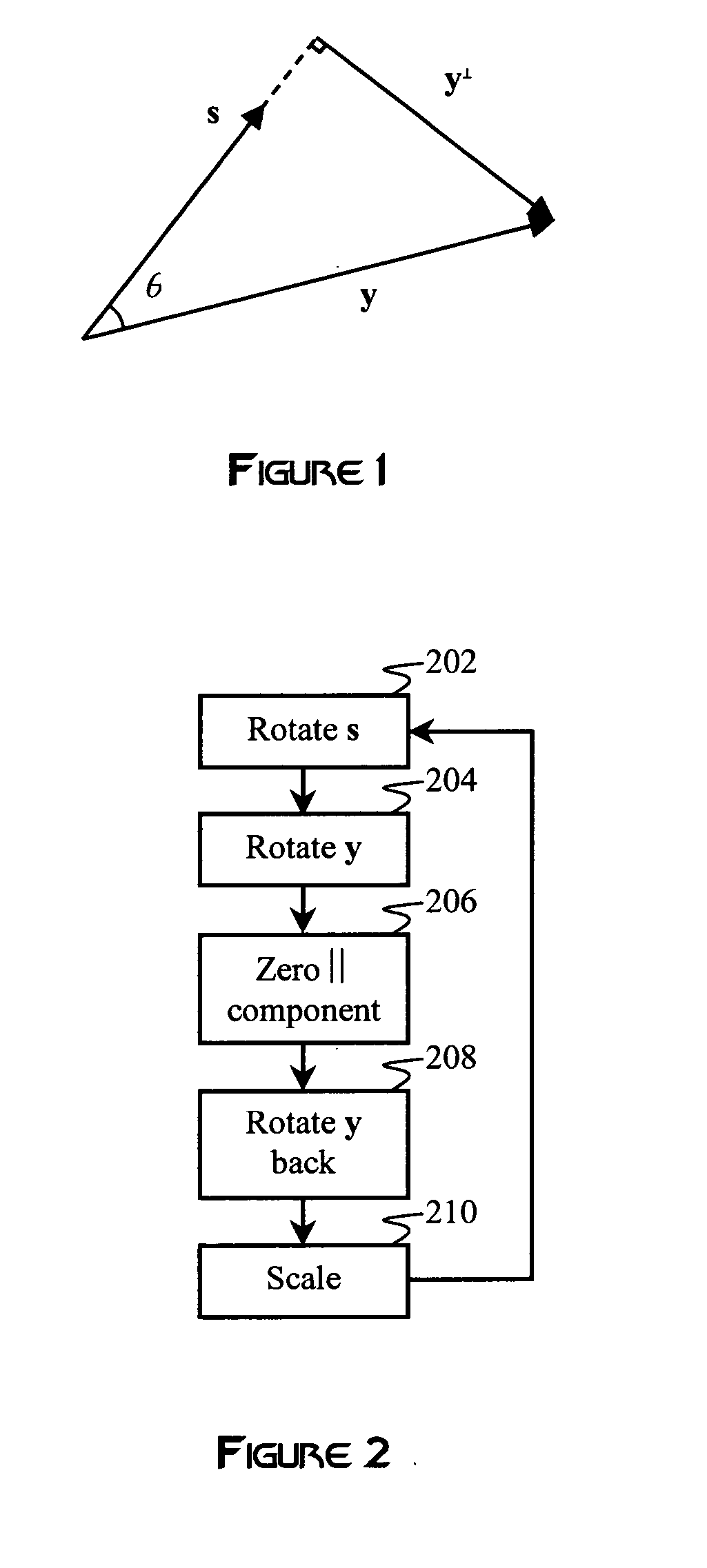
[0025]FIG. 1 is a vector diagram illustrating an example interference vector and measurement vector;

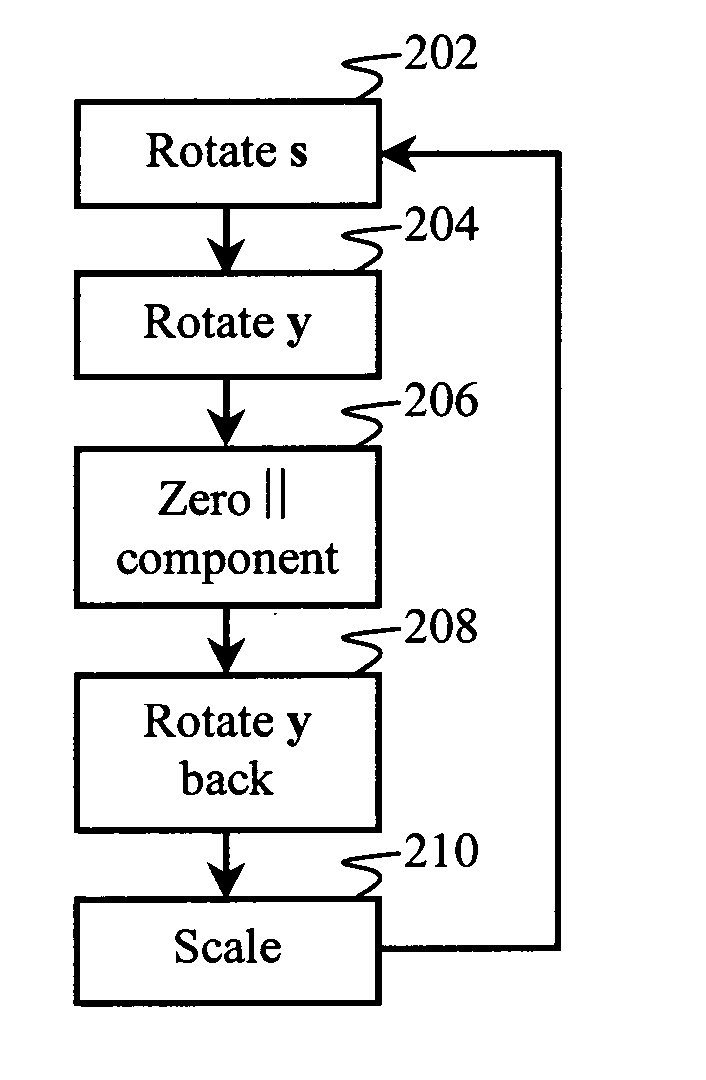
[0026]FIG. 2 is a flowchart illustrating an example method for performing an orthogonal CORDIC rotation in accordance with one embodiment;

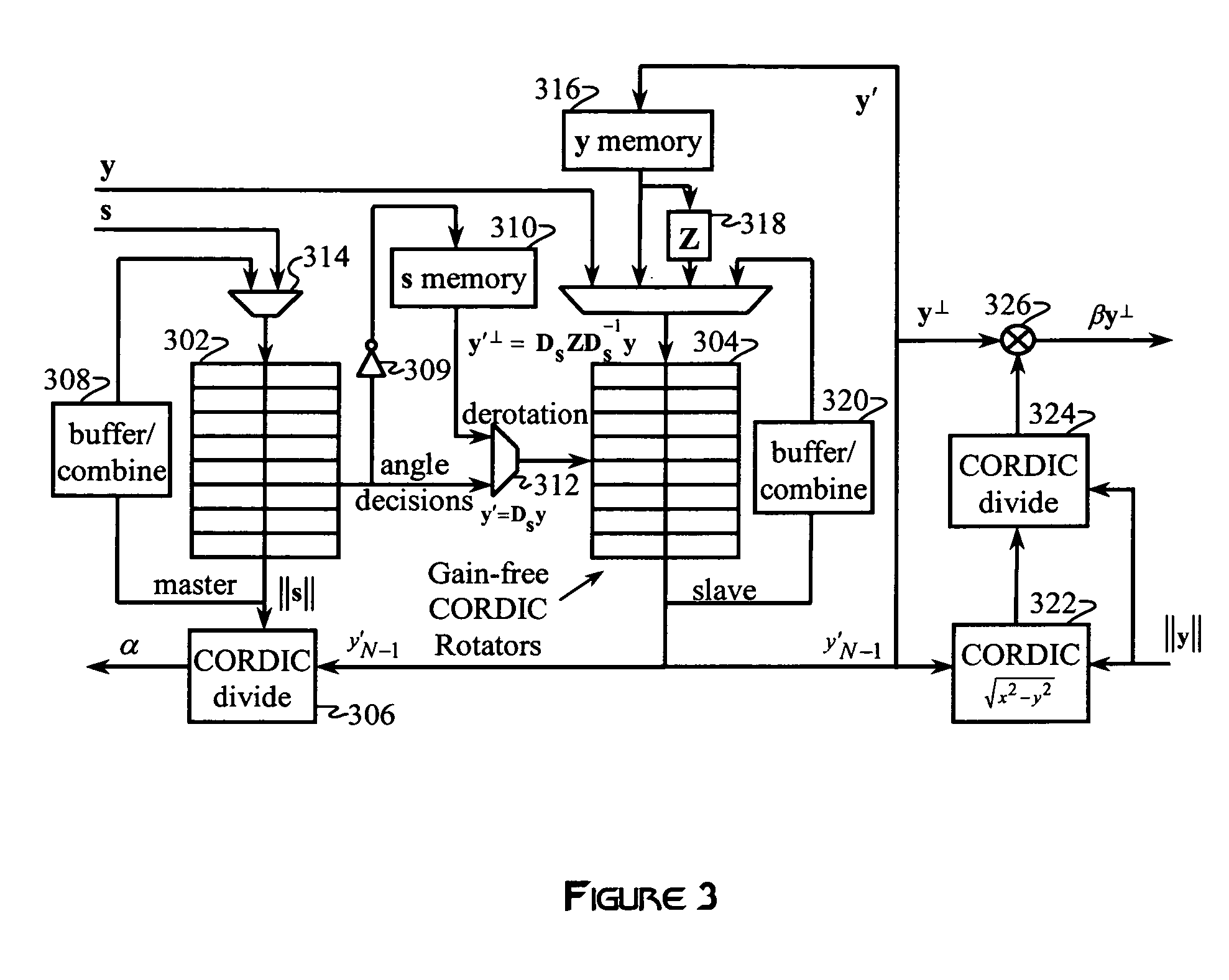
[0027]FIG. 3 is a diagram illustrating an example CORDIC rotator configured to implement the process of FIG. 2 on the vectors of FIG. 1 in accordance with one embodiment;

[0028]FIG. 4 is a graph illustrating the clock cycle efficiency as a function of a pipeline depth and a vector length for the pipeline included in the CORDIC rotator of FIG. 3;

[0029]FIG. 5 is a graph illustrating the clock cycle efficiency as a function of a pipeline depth versus vector length when a greedy scheme is implemented in the CORDIC rotator of FIG. 3;

[0030]FIG. 6 is a graph illustrating the chained operation...


PUM


Abstract

A CORDIC processor is configured to perform orthogonal or oblique CORDIC projections in order to cancel interference in a received signal. The CORDIC projection can be used to rotate an interference signal vector so that its only non-zero component is in the last Euclidean coordinate of the representative vector. A measurement vector is then subject to the same rotations as the interference vector. As a result of the rotation on the measurement vector, all components of the measurement vector parallel to the interference vector will be resolved onto the same coordinate as the rotated interference vector. The parallel components of the symbol vector can be cancelled by zeroing that coordinate, and the modified measurement vector can then be rotated back to its original coordinates, to produce an orthogonally projected version of the original measurement vector. Typically, the projection is onto a subspace that is orthogonal or oblique to an interference subspace, which may be one-dimensional.

Description

BACKGROUND [0001] 1. Field of the Invention [0002] The invention generally relates to wireless communication, and more particularly to interference cancellation in wireless communication systems. [0003] 2. Background of the Invention [0004] Combating interference is a primary objective in virtually all wireless communication systems. For example in a cellular wireless communication system, there are typically two types of interference that are of primary concern: inter-channel interference and intra-channel interference. [0005] Inter-channel interference occurs when multiple base stations communicating over the same frequency band interfere with each other. Intra-cell interference occurs when communication devices within a cell all communicate with the base station over the same carrier-frequency band and a common pseudo-noise carrier. In order to avoid interference between the devices, the communications from each device are coded with a covering code that allows the base station a...

Claims


Application Information

Patent Timeline
Patent Type & Authority Applications(United States)
IPC IPC(8): G06F7/38
CPCG06F7/5446
Inventor BREDEHOFT, LEO
Owner III HLDG 1
Learn More