Eye protection device, particularly against laser beams and high-intensity light beams

a laser beam and high-intensity light beam technology, applied in the field can solve the problems of rigid connection of wire bows, affecting the safety of eye protection devices, and previously known eye protection devices

Inactive Publication Date: 2007-06-14
LASERPOINT
View PDF9 Cites 6 Cited by
  • Summary
  • Abstract
  • Description
  • Claims
  • Application Information

AI Technical Summary

Benefits of technology

[0007] The present invention is based on the object of providing an eye protection device of the type cited at the beginning, which no longer has the sharp-edged mechanical pressure of the outer edge of the protective ...

Problems solved by technology

This previously known eye protection device is subject to the disadvantage that each protective shell is penetrated by a rivet connection and therefore laterally incident laser beams must be feared.
This eye protection device is provided with closed protective shells, but is connected to the disadvantage that the wire bow connected rigidly to the hooks via the spirals breaks off relatively easily and for persons having a large eye spacing, the eye area of the protective shells facing away from the wire bow folds outward when the wire bow is bent and must be pulled against the facial area of the affected wearing person surrounding the eyes and the eyelids accordingly by the tensile band with corresponding tensile forces.
Punctual strains thus arise due to the attachment hooks on the outer area and also due to the sprin...

Method used


Image

  • Eye protection device, particularly against laser beams and high-intensity light beams
  • Eye protection device, particularly against laser beams and high-intensity light beams
  • Eye protection device, particularly against laser beams and high-intensity light beams

Examples


Embodiment Construction

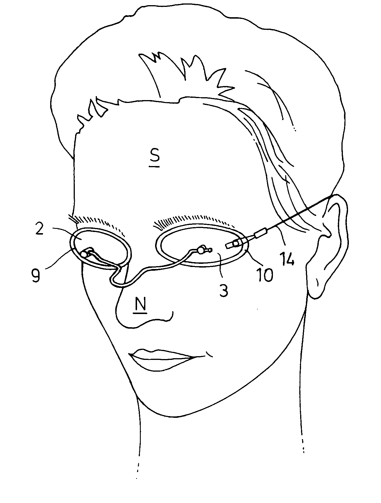
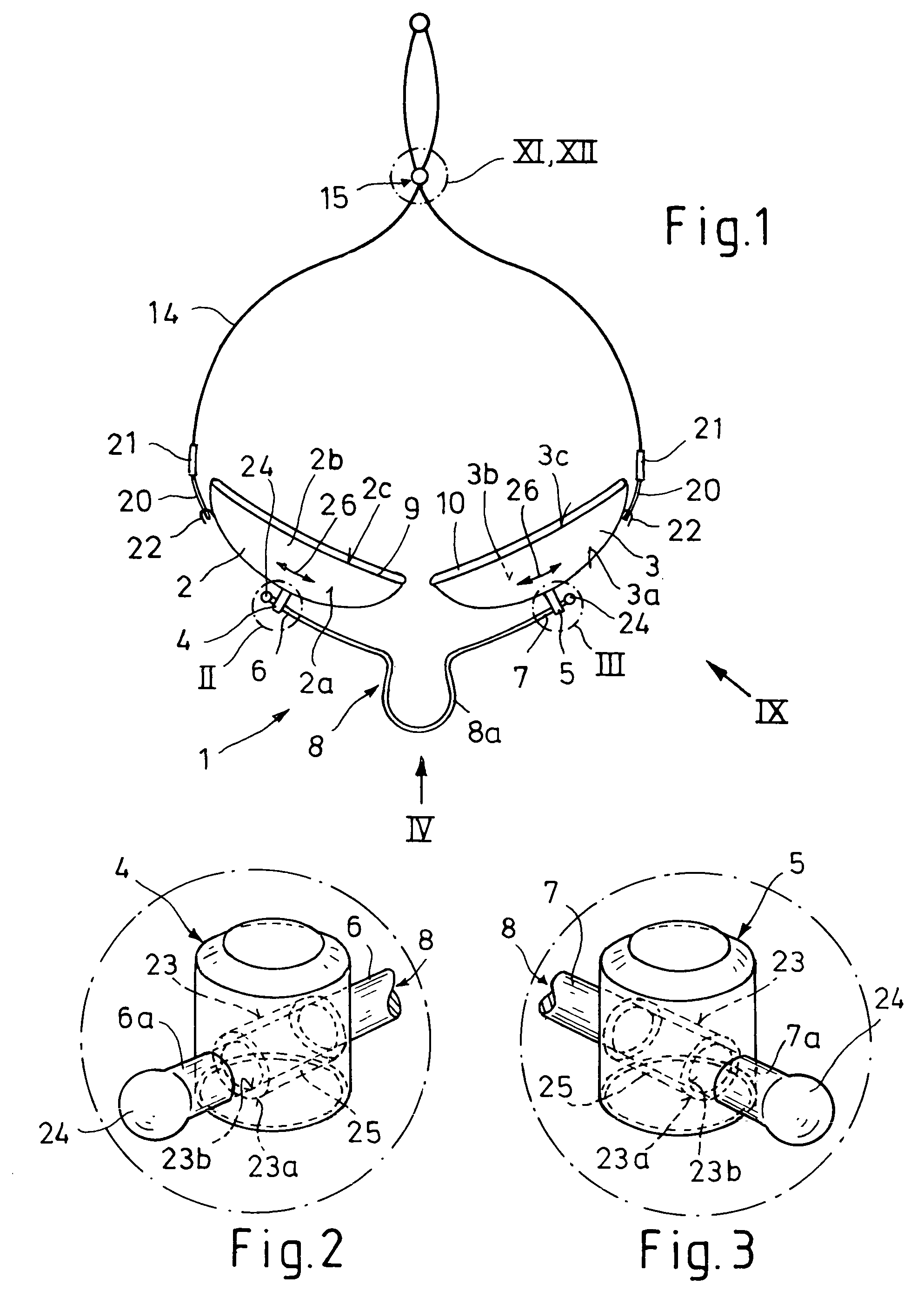
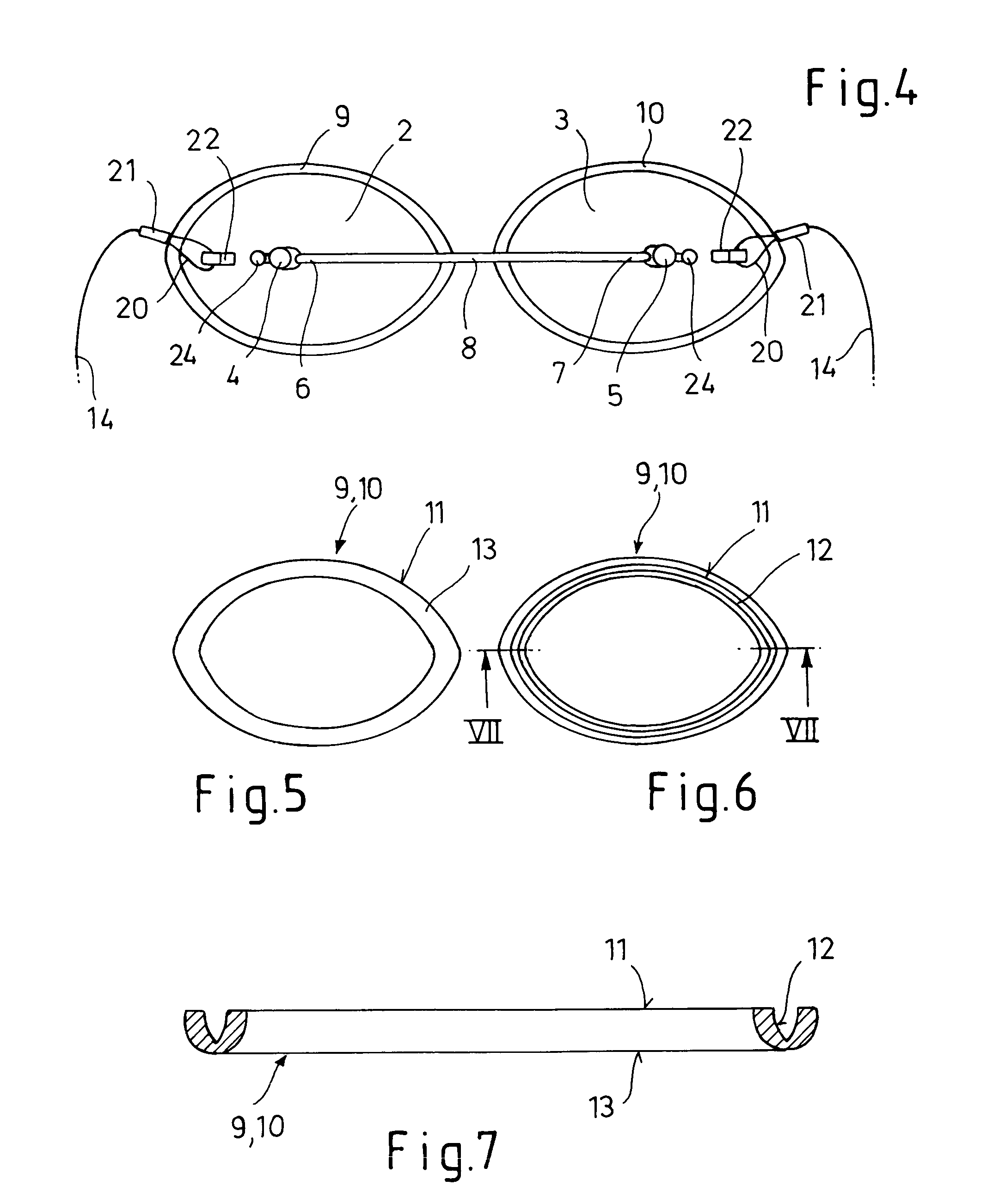
[0033] The eye protection device 1 shown in FIGS. 1 and 9 essentially comprises two protective shells 2 and 3 made of metal or ceramic, each of which has a projection 4, 5 in its central area, on which the ends 6, 7 of an entropy-elastic wire bow 8 are pivotably mounted. The protective shells 2, 3 are designed as convex on their outside 2a, 3a and concave on their inside 2b, 3b. The projections 4, 5 have a clear distance from the outer edges 2c and 3c of the protective shells 2 and 3.

[0034] Furthermore, the protective shells 2 and 3 are each enclosed on their outer edges 2c and 3c by an entropy-elastic ring 9,10, whose inner edge 11, facing toward the outer edge 2c, 3c is provided with a peripheral groove 12, which overlaps the outer edge 2c, 3c of the protective shells 2, 3 in its final position under entropy-elastic spring tension. The outer edge 13 of the entropy-elastic rings 9,10 is implemented as convex.

[0035] The entropy-elastic rings 9,10 for the protective shells 2, 3 com...


PUM


Abstract

An eye protection device (1) includes two internally concave and externally convex protective shells (2, 3), which cover the eyes and the eyelids of a wearing person and are connected by an elastic wire bow (8), whose ends (6, 7) are attached to a projection (4, 5) on the protective shells (2, 3) at a distance from their outer edge (2c, 3c). The eye protection device no longer has the sharp-edged mechanical pressure of the outer edge of the protective shells, which feels unpleasant, and nonetheless ensures a secure seal of the outer edge of the protective shells in relation to the facial skin. Each protective shell (2, 3) is completely enclosed on its outer edge (2c, 3c) by an opaque, entropy-elastic ring (9, 10) having high heat resistance and the band-shaped holding unit (14) is provided with an adjustment and locking device (15), using which the untensioned length of the holding unit (14) may be lengthened or shortened rapidly, the holding unit (14) forming a joint spring (9, 10, 14) in connection with the entropy-elastic rings (9, 10) of the protective shells (2, 3), whose spring pre-tension is adapted to the mechanical pressure compatibility of the wearing person via the adjustment and locking device (15).

Description

TECHNICAL FIELD [0001] The present invention relates to an eye protection device, particularly against laser and light beams, comprising two internally concave and externally convex protective shells, which cover the eyes and the eyelids of a wearing person and are connected by an elastic wire bow, whose ends are attached to a projection on the protective shells at a distance from the outer edge and whose middle part maintains a clear interval to the nose, the protective shells being held on the head of the wearing person using an elastic holding unit. BACKGROUND ART [0002] A known eye protection device of this type is known from DE 101 06 668 C2. In this embodiment, the wire bow is made of a thin, break-proof wire, also having high torsion elasticity, made of a titanium-nickel alloy, whose free ends are permanently bonded to the convex outside of the completely closed protective shells by laser welding, soldering, or gluing. [0003] Eye protection devices of this type are used not o...

Claims


Application Information

Patent Timeline
IPC IPC(8): A61F9/02
CPCA61F9/04
Inventor BEYER, ANTONIUS
Owner LASERPOINT
Why Eureka
Try Eureka