Wire saw

a wire saw and wire tension technology, applied in the field of wire saws, can solve the problems of high cost and large fluctuations in the tension of the wire row in the swinging of the wire row, and achieve the effects of preventing occurrence, and reducing the cost of the wire reel driving motor

Inactive Publication Date: 2007-06-14
TAKATORI
View PDF3 Cites 17 Cited by
  • Summary
  • Abstract
  • Description
  • Claims
  • Application Information

AI Technical Summary

Benefits of technology

[0034] Furthermore, in any of the inventions, because it is possible to accommodate the tension fluctuations in the wire at the time of swinging of the row of wires, it becomes unnecessary to take the tension fluctuations due to swinging motion into consider

Problems solved by technology

Therefore, challenges in the wire saw are to reduce the diameter of the wire A and to increase a linear velocity of the wire A from a viewpoint of improvement in manufacturing efficiency.
However, in the swinging mec

Method used


Image

  • Wire saw
  • Wire saw
  • Wire saw

Examples


first embodiment

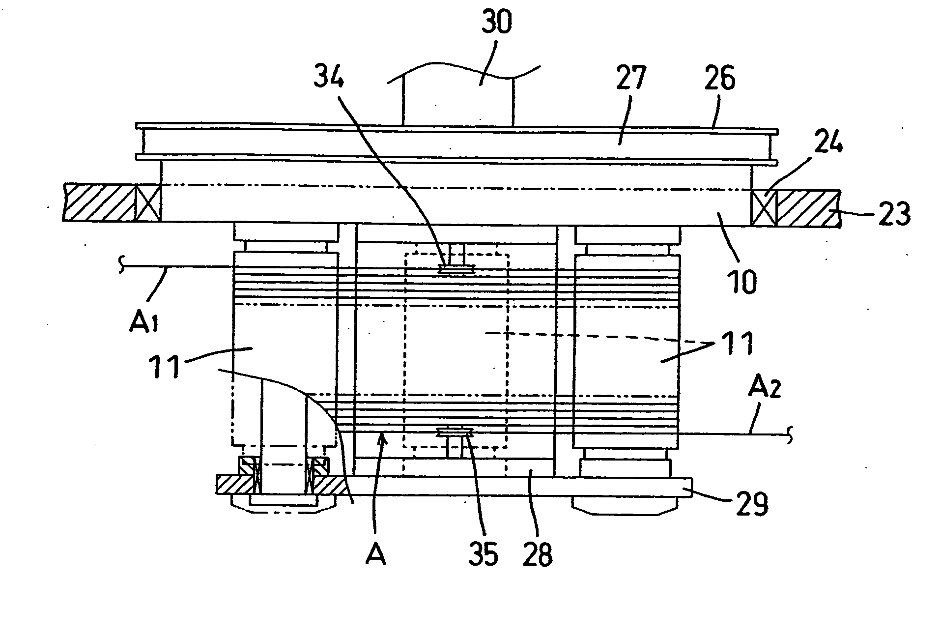
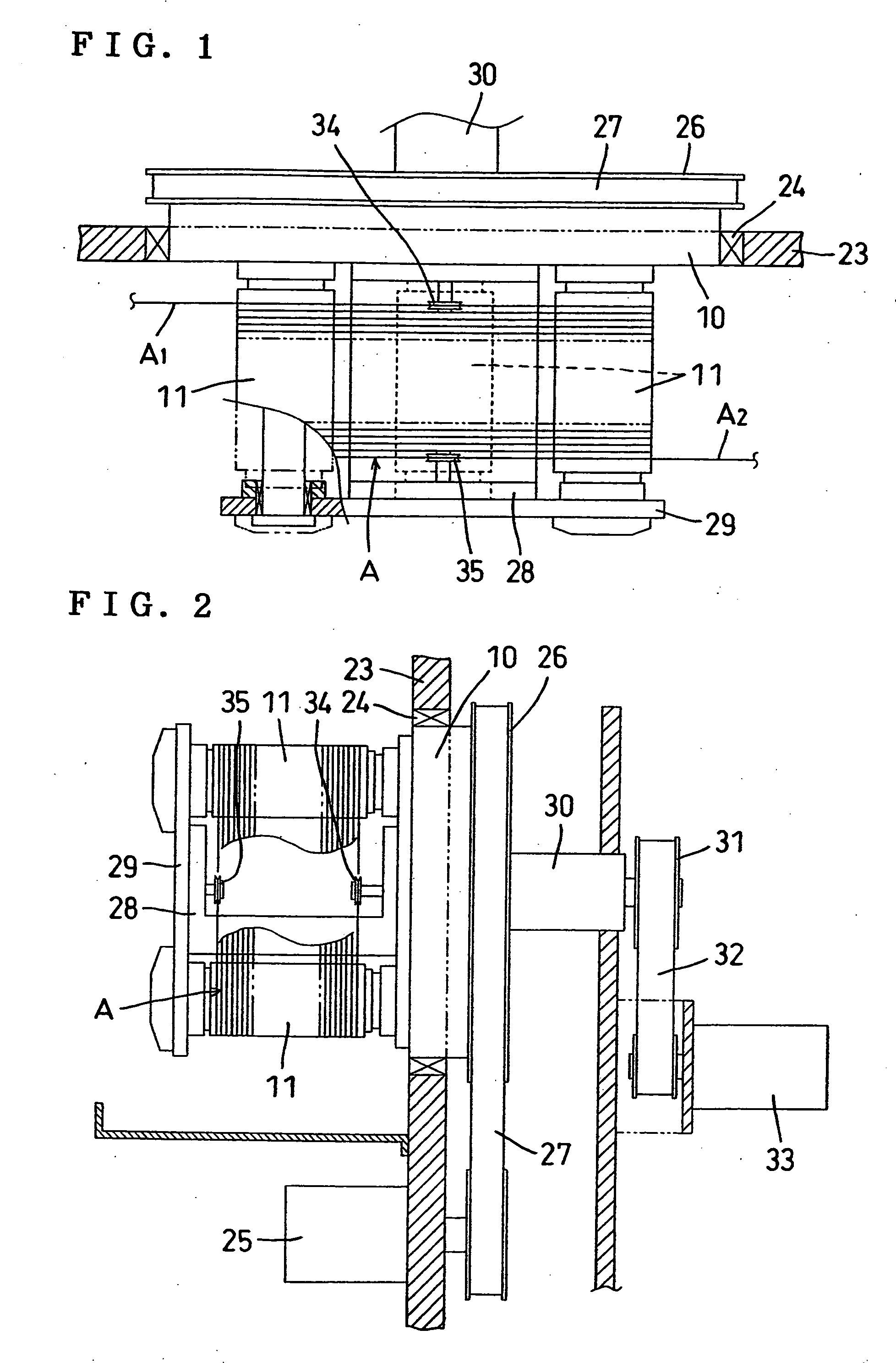
[0048] FIGS. 1 to 3C show the invention. A feed side pulley 34 for guiding feed side wire A1 going into the work rollers 11 to the work rollers 11 and a retrieving side pulley 35 for guiding retrieving side wire A2 going out of the work rollers 11 to an outside are disposed coaxially on an axial center of rotation of the swinging disk 10.

[0049] The feed side pulley 34 and the retrieving side pulley 35 are mounted to opposed faces of the fixed frame 28 so as to be coaxial with each other on the axial center of rotation of the swinging disk 10.

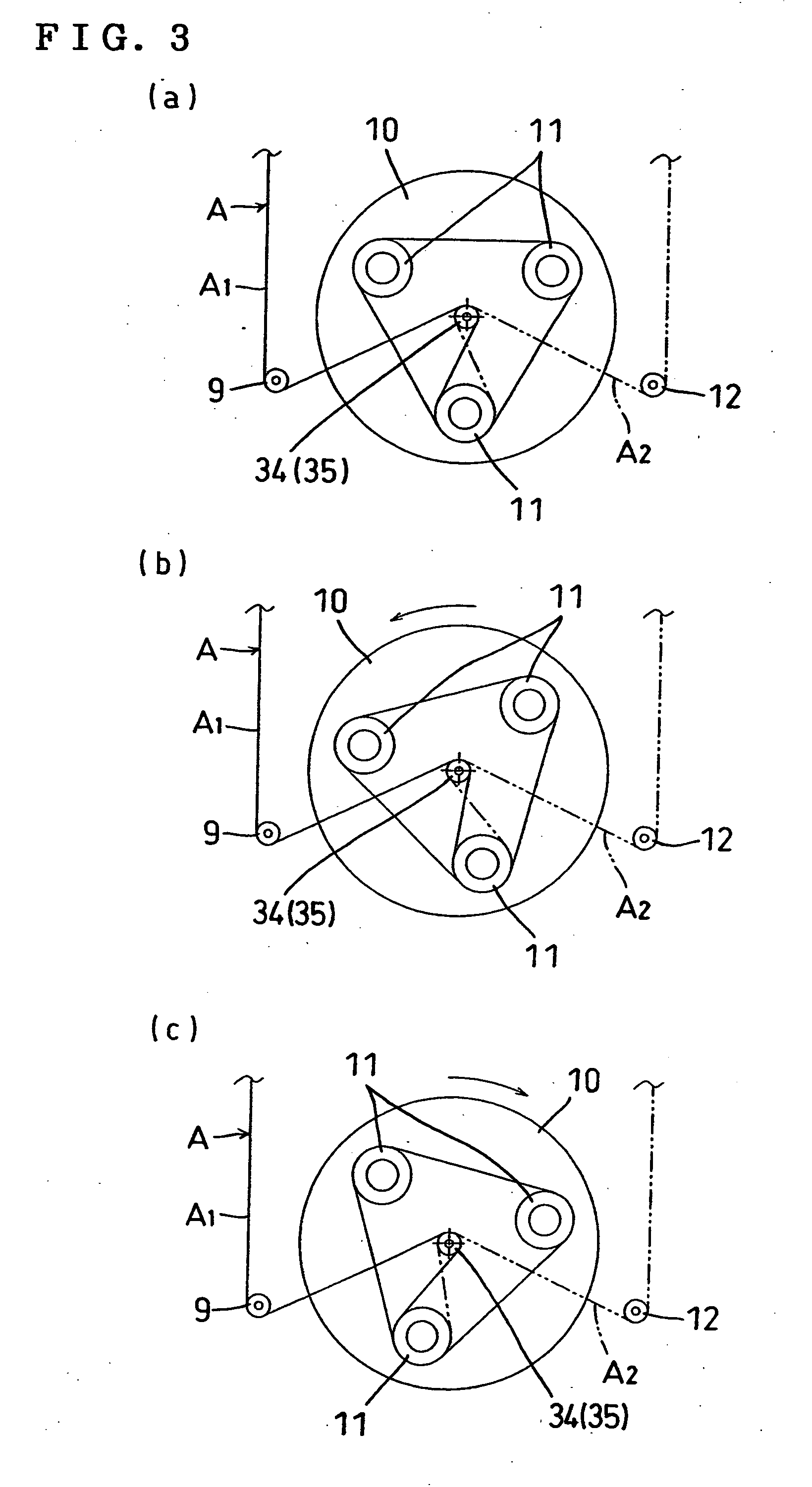
[0050]FIGS. 3A to 3C show a state of actuation of the first embodiment. As shown in FIG. 3A, the feed side wire A1 passes from an outside fixed guide pulley 9 to the feed side pulley 34 and enters the work roller 11 positioned in a lower position and the retrieving side wire A2 is drawn out from the work roller 11 in the lower position through the retrieving side pulley 35 and an outside fixed guide pulley 12 when a workpiece cutting portion lo...

second embodiment

[0053] FIGS. 4 to 5C show the invention. A feed side pulley 34 on a feed side of wire A to work rollers 11 and a retrieving side pulley 35 on a retrieving side of the wire A from the work rollers 11 are provided in such a manner as to turn together with the swinging disk 10. On an outer side of the feed side pulley 34, an outer pulley 9a for guiding feed side wire A1 to the feed side pulley 34 and an outer pulley 9b for guiding the wire A1 from the feed side pulley 34 to the work rollers 11 are fixed and disposed, respectively. On an outer side of the retrieving side pulley 35, an outer pulley 12b for guiding retrieving side wire A2 from the work rollers 11 to the retrieving side pulley 35 and an outer pulley 12a for guiding the wire A2 from the retrieving side pulley 35 to an outside are fixed and disposed, respectively.

[0054] The feed side pulley 34 is mounted to an outer peripheral portion of the swinging disk 10 and in a position below the row of wires positioned in an upper pos...

third embodiment

[0059] FIGS. 6 to 7C show the invention. On outer sides of the swinging disk 10, a feed side pulley 34 for guiding feed side wire A1 to the work rollers 11 is provided in a position on a feed side where wire A goes into the work rollers 11 and a retrieving side pulley 35 for guiding retrieving side wire A2 to an outside is provided in a position on a retrieving side where the wire A goes out of the work rollers 11 so that the pulleys 34, 35 can move in a tension applying direction and a tension lessening direction of the wire A. In turning of the swinging disk 10 in a reciprocating manner, the pulley on the side where the tension in the wire A reduces is controlled in the tension applying direction and the pulley on the side where the tension in the wire A increases is controlled in the tension lessening direction.

[0060] As shown in FIG. 6, the feed side pulley 34 and the retrieving side pulley 35 are supported to be able to move horizontally by rails 38 and sliders 39 of guide fram...


PUM

PropertyMeasurementUnit
Distanceaaaaaaaaaa
Tensionaaaaaaaaaa
Velocityaaaaaaaaaa

Abstract

The invention provides a wire saw in which wire tension fluctuations occurring in swinging of a row of wires can be accommodated to thereby increase a velocity of the wire and to carry out cutting with efficiency and precision by utilizing swinging of the row of wires even with thin wire. In the wire saw having the row of wires formed by winding the wire about a plurality of work rollers provided to a swinging disk many times, for pushing a workpiece against the row of wires caused to reciprocate or travel in one direction at high velocity to cut the workpiece into a plurality of pieces, and for swinging the row of wires in cutting of the workpiece, a feed side pulley for guiding feed side wire going into the work rollers to the work rollers and a retrieving side pulley for guiding retrieving side wire going out of the work rollers to an outside are disposed coaxially on an axial center of rotation of the swinging disk so that the tension fluctuations do not occur in the wire even if the row of wires swings.

Description

BACKGROUND OF THE INVENTION [0001] 1. Field of the Invention [0002] The present invention relates to a wire saw having improved cutting efficiency and accuracy by swing row of wires in pushing a workpiece against the row of wires reciprocating or traveling in one direction at high speed to cut the workpiece and more particularly to a wire saw in which occurrence of tension fluctuations in wires at a time of swinging of the row of wires is prevented to prevent occurrence of cuts of the wire to obtain stable traveling performance. [0003] 2. Description of the Related Art [0004] Conventionally, in a wire saw in which a row of wires are swung in cutting a workpiece, as shown in FIG. 9, wire A drawn out from a feed side reel 1 is led via a feed side traverser 3 driven by a motor 2 and a plurality of guide pulleys 4 to a tension mechanism 7 formed of an encoder 5 and a tension arm 6, a load cell 8 for measuring tension in the wire A, and a plurality of guide pulleys 9 and then wound aroun...

Claims


Application Information

Patent Timeline
IPC IPC(8): B28D1/08
CPCB23D57/0061B23D57/0069B28D5/045
Inventor KOMEDA, TATSUYA
Owner TAKATORI
Why Eureka
Try Eureka