Wafer-type direct-acting valve

Active Publication Date: 2007-06-14
KANE KOUGYOU
View PDF11 Cites 4 Cited by
  • Summary
  • Abstract
  • Description
  • Claims
  • Application Information

AI Technical Summary

Benefits of technology

[0014] Therefore, according to the present invention, the connecting end portions and the pipe flanges can be easily mated in a tightly sealed state without any effort as described above. In a conventional method, when installing a sealing member such as a gasket between the connecting end portions and the pipe flanges, the sealing member must be positioned in a state suspended in the air on the same axis of the pipe flanges and at a position between the pipe flanges and the connecting end portions having a diameter smaller than the

Problems solved by technology

However, probably because the structure of the direct-acting valve is not simple as compared with a single-plate check

Method used


Image

  • Wafer-type direct-acting valve
  • Wafer-type direct-acting valve
  • Wafer-type direct-acting valve

Examples


Example

[0019] Hereinafter, an example as an embodiment of the present invention will now be described based on the drawings.

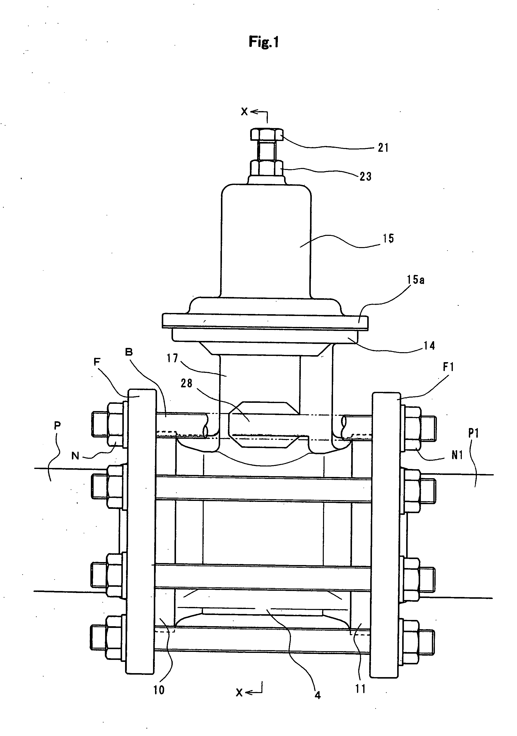
[0020]FIG. 1 is a front view showing a piping state of a wafer-type direct-acting valve.

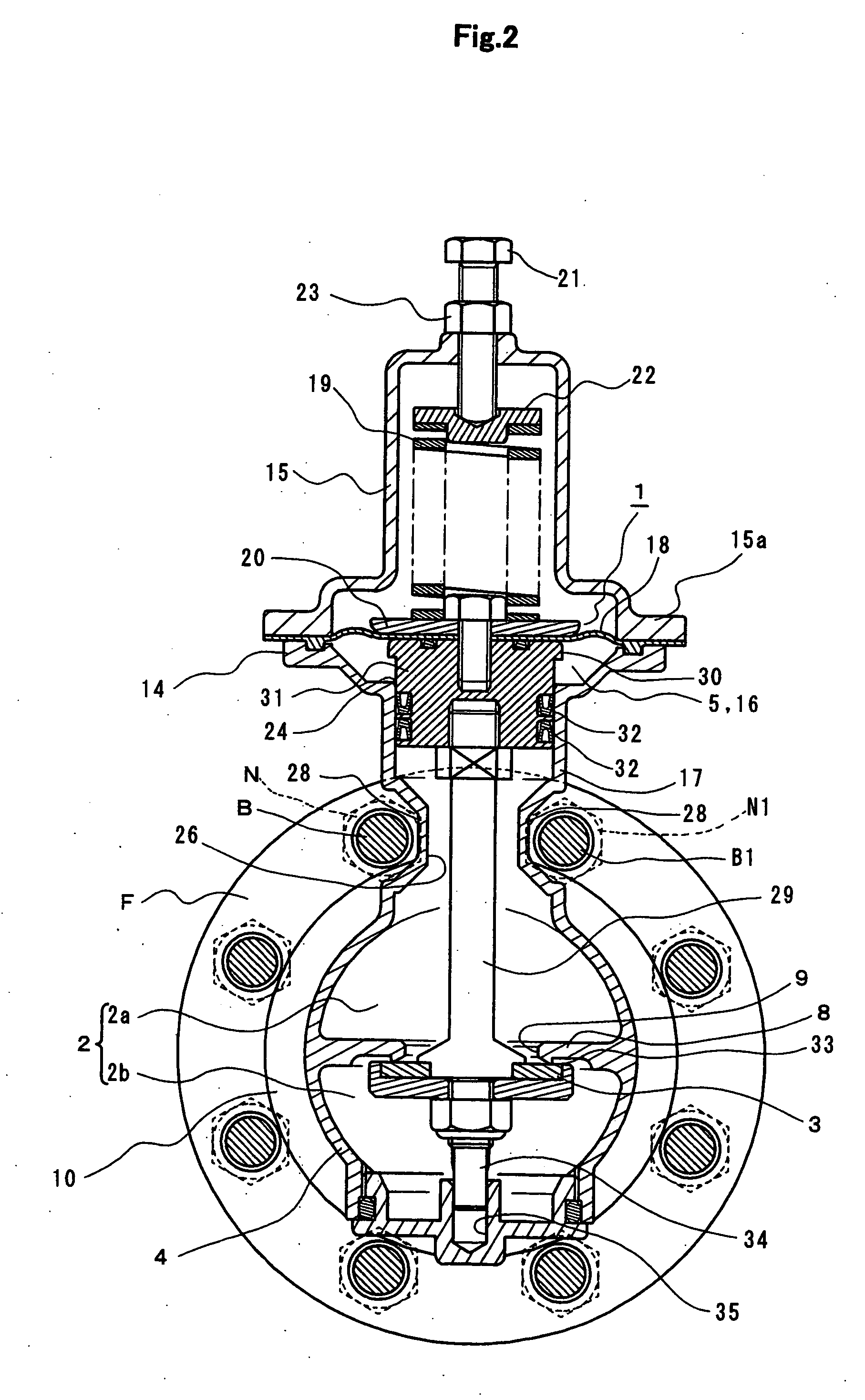
[0021]FIG. 2 is a cross-sectional view along the line X-X of FIG. 1.

[0022]FIG. 3 is a longitudinal sectional view along the line X-X of FIG. 1.

[0023]FIG. 4 is an enlarged cross-sectional view along the line Y-Y of FIG. 3, partly omitted.

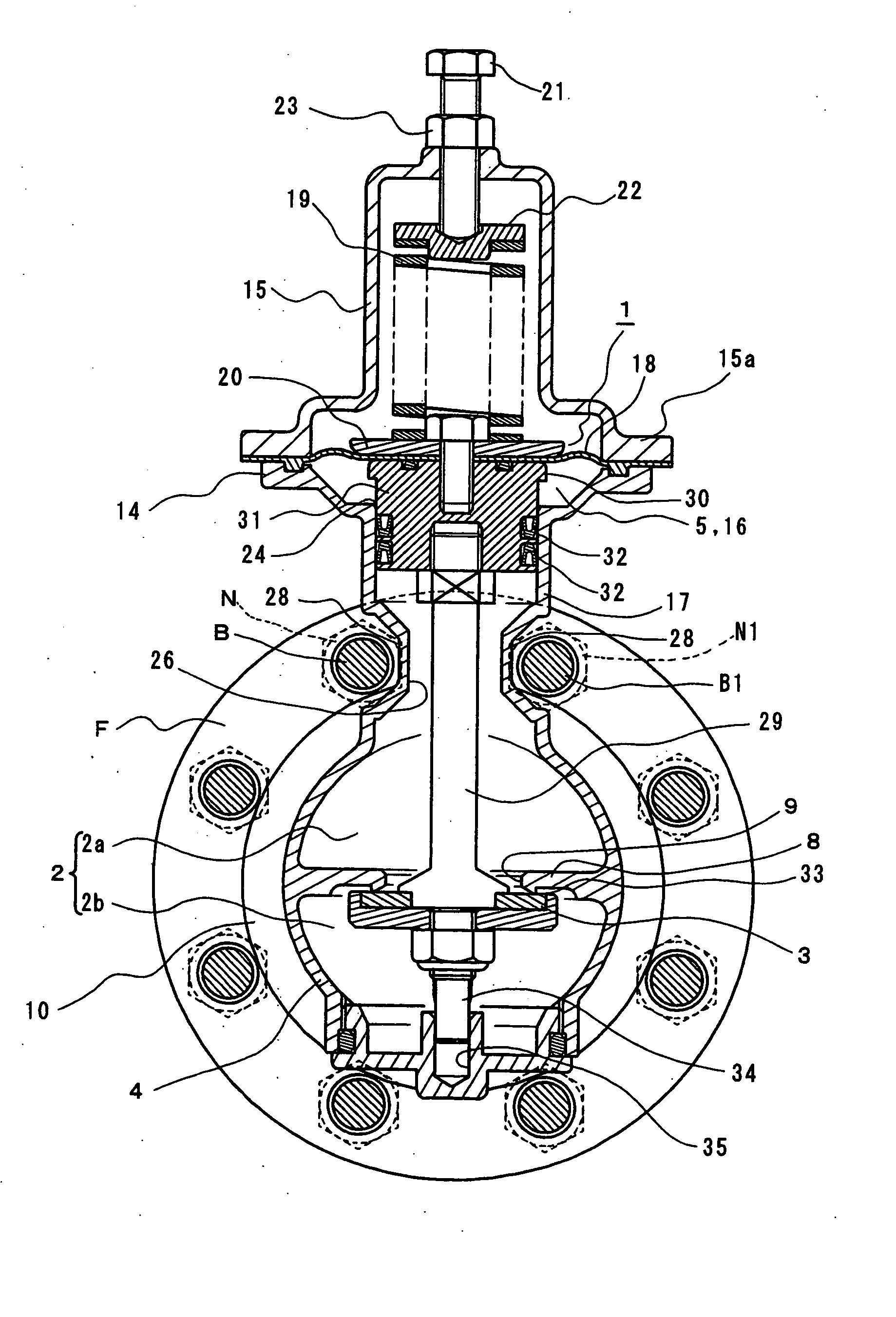
[0024] This valve is a direct-acting valve, including a driving section 1 which operates when it senses a primary pressure or a secondary pressure, and a valve body 3 communicated with the driving section 1 and operated to open and close a flow path 2. The illustrated valve shows a direct-acting pressure reducing valve.

[0025] The structure of this direct-acting pressure reducing valve is as follows. A valve box 4 includes a flow path 2 (including a primary flow path 2a and a secondary flow path 2b), and a driving section 1 incorporated into th...


PUM


Abstract

In the direct-acting valve of the present invention, no flange is formed in the valve box and the piping is achieved by interposing the valve box between pipe flanges.
The direct-acting valve of the present invention includes: a driving section 1 that operates by sensing a primary pressure or a secondary pressure; and a valve body 3 communicating with the driving section 1 to open and close a flow path 2. A valve box 4 of the valve is sandwiched between pipe flanges F and F1 tightened by bolts B, B1 and nuts N, N1 . . . . Connecting end portions 10 and 11 to be mated with pipe flanges F and F1 that respectively have an inlet and an outlet 6 and 7 of the flow path 2 are made to be flangeless. A cover flange neck 17 is extended upward from the valve box 4 is formed so as to be interposed between the bolts B and B1 which are provided between the pipe flanges F and F1 and adjacent to each other on the circumference of the pipe flanges F and F1.

Description

FIELD OF THE INVENTION [0001] The present invention relates to a wafer-type direct-acting valve in which a direct-acting valve, such as a pressure adjusting valve such as a pressure reducing valve, a solenoid valve, and a constant water level valve, is sandwiched between pipe flanges and is fixed by bolts and the like penetrated through the pipe flanges. DESCRIPTION OF THE RELATED ART [0002] Conventionally, there is a wafer-type valve in which a valve box is interposed between pipe flanges and the pipe flanges are fixed by tightening by bolts and nuts. As this type of valve, there are a single-plate check valve and a flangeless butterfly valve. In these valves, a thin disc-shaped valve body swings or rotates in a thin cylindrical valve box through which a fluid flows lineally, so as to open and close the flow path. These valves are relatively simple in the structures and operations (for example, see Non-patent Document 1). [0003] On the other hand, there is a direct-acting valve in ...

Claims


Application Information

Patent Timeline
IPC IPC(8): F16K25/00
CPCF16K27/08F16K41/12Y10T137/7504Y10T137/7825F16K17/06F16K27/0236
Inventor OCHIAI, MASARUYAMAGUCHI, HISAYUKI
Owner KANE KOUGYOU
Why Eureka
Try Eureka