U-turn signal device for motor vehicles

a technology for turning signals and motor vehicles, applied in signalling/lighting devices, optical signalling, vehicle components, etc., can solve the problems of high rate of collision accidents, number of traffic accidents, and statistically the most dangerous component of turning signals, etc., to achieve convenient installation and use, easy retrofitability, and easy adaptation

Inactive Publication Date: 2007-06-14
QUACH TUAN KIM +2
View PDF8 Cites 38 Cited by
  • Summary
  • Abstract
  • Description
  • Claims
  • Application Information

AI Technical Summary

Benefits of technology

[0013] An advantage of the present invention is that the U-turn signal device is easily retro-fittable to existing after-market vehicles.
[0014] Another advantage of the present invention is that the U-turn signal device preferably uses LEDs which do not wear out like conventional bulbs
[0015] And another advantage of the present invention is that one embodiment of the U-turn signal device uses flexible LEDs which are more easily adapted to a variety of car models.
[0016] A further advantage of the present invention is that the U-turn signal device provides a U-turn signal for motor vehicles which is convenient to install and use.
[0017] A yet further advantage is that the present invention is that the U-turn signal device provides a U-turn signal which requires reduced maintenance.
[0018] Yet another advantage of the present invention is that the U-turn signal device includes an IC circuit which produces multiple modes of activity for indicating a U-turn, a stop light and a left turn.

Problems solved by technology

These many running vehicles can cause numerous traffic accidents.
Performing a U-turn is considered statistically the most dangerous component in a great variety of accidents, even if most of local ordinances restrict making a U-turn on some stream of traffic.
The statistical incidence of U-turns still shows that the rate of collision accidents is extremely high because other drivers often misunderstand the signal for a U-turn as a left turn.
It requires replacement of lamp since its life span is limited.
It has utility of combining the U-turn signal to the conventional signaling system in new automobile development, but for after-market vehicle signaling assembling, it is not convenient.
Even if it does not need an additional switch to operate the signal device, there is still the same problem as above.

Method used


Image

  • U-turn signal device for motor vehicles
  • U-turn signal device for motor vehicles
  • U-turn signal device for motor vehicles

Examples


Embodiment Construction

[0033] The following detailed description is of the best modes of carrying out the invention. The description is not to be taken in a limiting sense, but is made merely for the purpose of illustrating the general principles of the invention, since the scope of the invention is best defined by the appended claims.

[0034] The present invention includes various types which pertain to all new automobile development, and more particularly for an after-market signaling assembly.

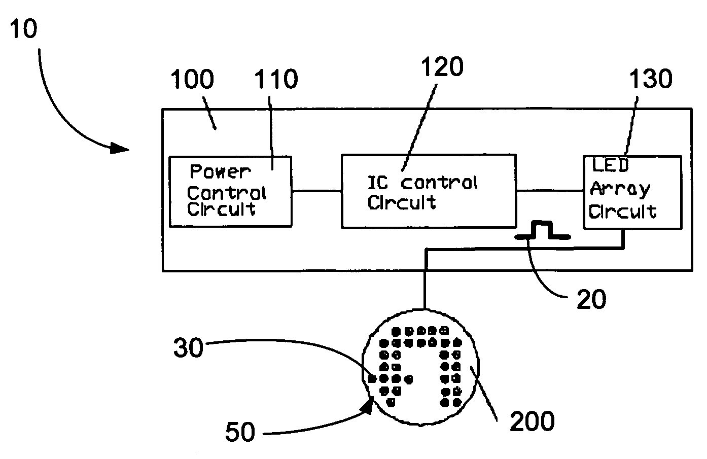
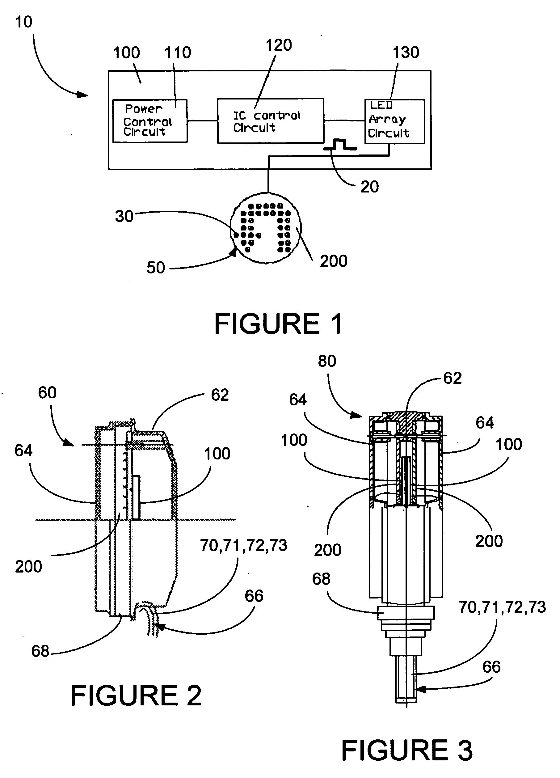
[0035]FIG. 1 shows a block diagram of the major elements of the control circuit 100 of the U-turn signal 10 of the present invention. The control circuit 100 includes power control circuit 110, programmed IC control circuit 120 and LED array control circuit 130. Power for this circuit is supplied by the existing power supply of the vehicle. This control circuit 100 produces a variety of signals 20 which operates the LED array 200, causing it to flash and move in one of a variety of specific frequencies and directi...


PUM


Abstract

U-turn signaling device for vehicles is disclosed, which includes an LED array, and an integrated circuit control circuit which is produces LED activation control signals. These control signals activate the LED array to produce at least three modes of activity including a tail light mode, a turn mode and a U-turn mode in response to activation signals from the tail light, turn signal and U-turn signal respectively. The LED array can be a portable LED array, an embedded LED array or a double-sided LED array. The LED array is a preferably a combo LED array and further includes a monitor screen, which may be mounted in the dashboard of the vehicle, and may include a multi-position turn signal switch. Also disclosed is a flexible U-turn signal device, which may be activated by a wireless remote control switch.

Description

[0001] The following claims priority from provisional patent application 60 / 677,486, filed May 3, 2005 to the same inventors. TECHNICAL FIELD [0002] The present invention relates generally to the field of signaling devices for motor vehicles, and more particularly to a U-turn signaling device for motor vehicles. BACKGROUND OF THE INVENTION [0003] The present invention relates to a motor vehicle signaling device and more particularly to a vehicle U-turn Signal Device to provide a U-turn Signal when a vehicle intends to make a U-turn. [0004] Three hundred twenty million motor vehicles are registered in the United States in the year 2004. These many running vehicles can cause numerous traffic accidents. Performing a U-turn is considered statistically the most dangerous component in a great variety of accidents, even if most of local ordinances restrict making a U-turn on some stream of traffic. The statistical incidence of U-turns still shows that the rate of collision accidents is ext...

Claims


Application Information

Patent Timeline
Patent Type & Authority Applications(United States)
IPC IPC(8): B60Q1/34
CPCB60Q1/34B60Q1/381
Inventor QUACH, TUAN KIMQUACH, TONYGUO, YANXIA
Owner QUACH TUAN KIM
Why Eureka
Try Eureka