Memory management for systems for generating 3-dimensional computer images

a technology of memory management and computer generated images, applied in the direction of memory adressing/allocation/relocation, image data processing, instruments, etc., can solve the problems of reducing the storage requirements of display lists, preventing considerable optimisation, and increasing the complexity of scenes which it is necessary to render using 3-d graphic systems. achieve the effect of reducing the memory bandwidth consumed

Inactive Publication Date: 2007-06-14
IMAGINATION TECH LTD
View PDF10 Cites 51 Cited by
  • Summary
  • Abstract
  • Description
  • Claims
  • Application Information

AI Technical Summary

Benefits of technology

[0010] Preferred embodiments of the present invention provide a method of managing the display list in such a manner as to impose an upper bound on the memory consumption, whilst at the same time attempting to minimise the memory bandwidth consumed by the system. This may be achieved by storing the state of the system (ISP and TSP) to memory before rendering of a tile is complete, and reloading this state at a later time in order to finish the rendering. We refer to this technique as “z / frame buffer load and store”.

Problems solved by technology

However, it also precludes the considerable optimisation which are possible with the type of rendering described in our British Patent No. 2281682 and improved on in our British Patent Application No. 2298111.
The complexity of scenes which it is necessary to render using 3-D graphic systems is increasing as hardware becomes more powerful.
However, this presents a problem for display list based renderers because the display list storage requirements also increase.
Image corruption of this sort is no longer considered acceptable.
The cost of memory, which is not falling as fast as scene complexity is rising, makes increasing the amount of memory in the system unfeasible.

Method used


Image

  • Memory management for systems for generating 3-dimensional computer images
  • Memory management for systems for generating 3-dimensional computer images
  • Memory management for systems for generating 3-dimensional computer images

Examples


Embodiment Construction

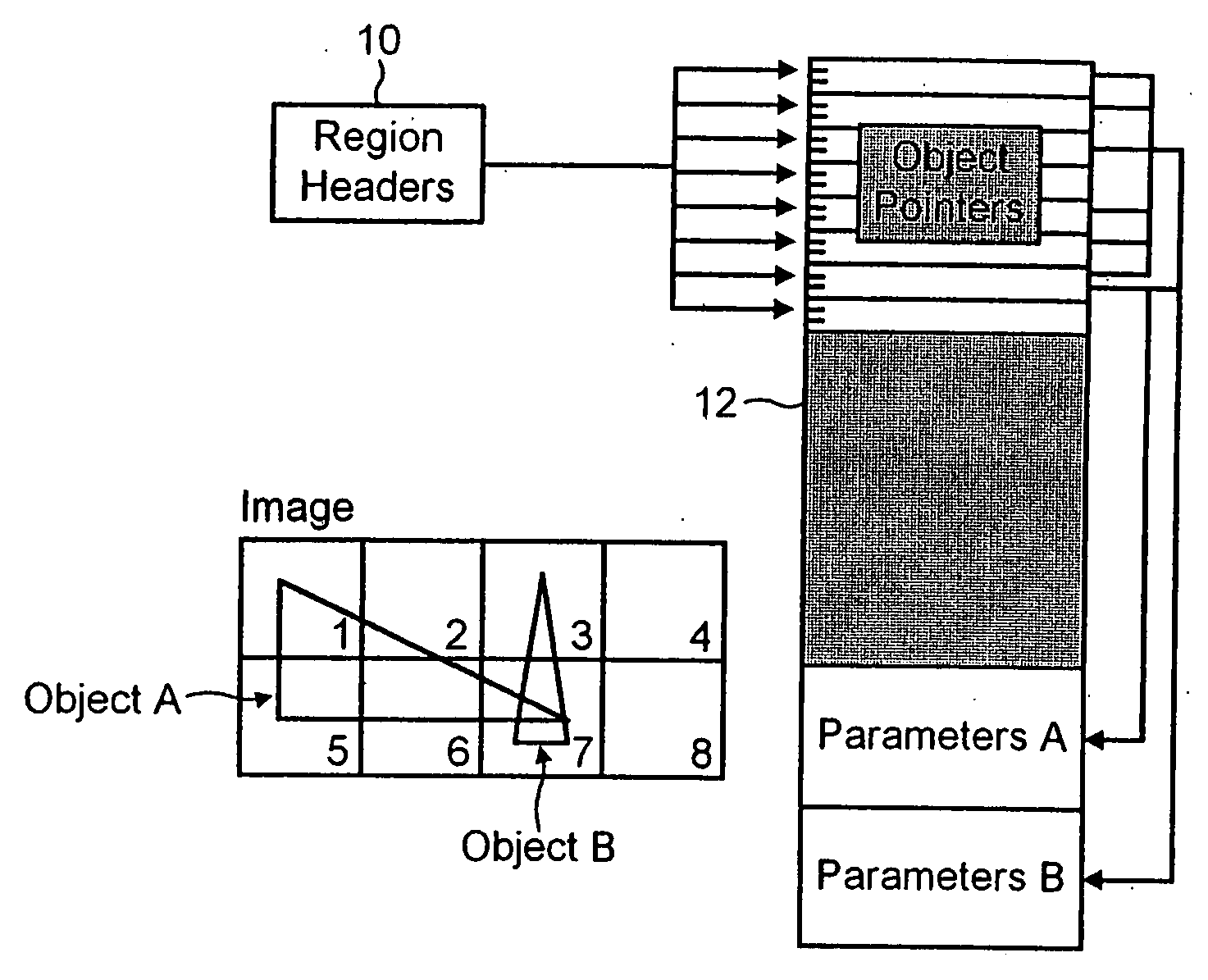
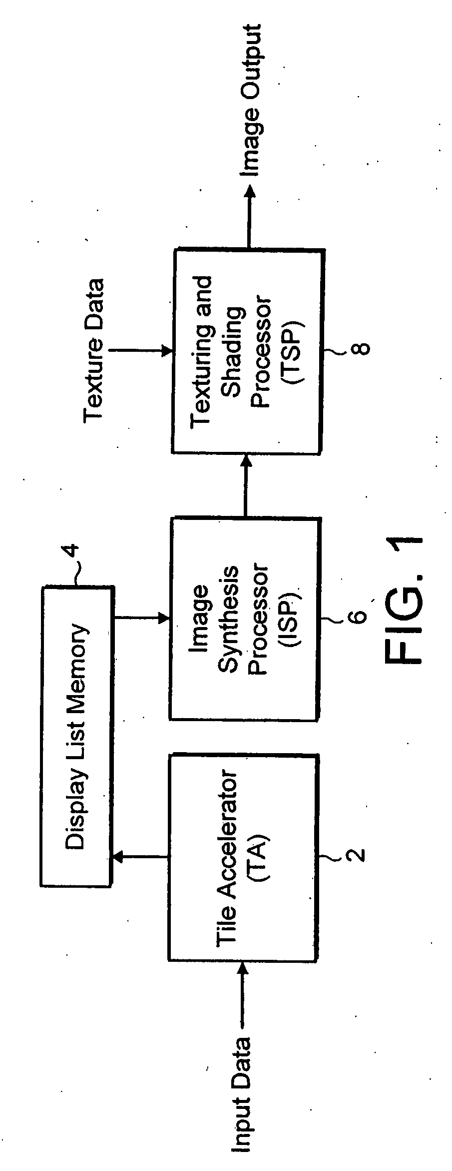
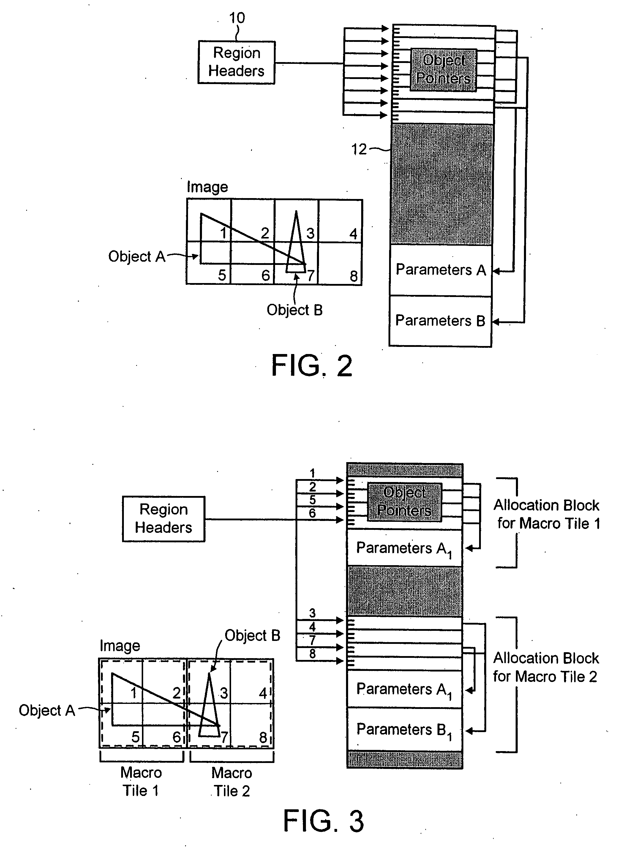
[0026] In the system of FIG. 1, polygons which are to be displayed are broken down into planar triangles. The data representing these is transformed by either hardware or software into a screen space representation and is then stored in local memory. The tiling process then performed by the tile accelerator 2 creates a list of pointers to the transformed triangle data for each tile in the scene. This is then stored in the display list along with parameters pertaining to the object of which the triangle is a portion. This is shown schematically in FIG. 2 in which the region headers 10 correspond to the identities of the tiles 1-8 shown in the Figure. As can be seen, the tiles cover two triangles named object A and object B. Object A is visible in tiles 1, 2, 5, 6 and 7 and object B is visible in tiles 3 and 7.

[0027] A display list 12 receives from the tile data for the objects visible in each tile and links are provided to the parameters associated with each object, namely parameter...


PUM


Abstract

A 3-dimensional computer generated image is generated by subdividing the image into a plurality of rectangular areas. Object data for each rectangular area is loaded into a display list memory (4) until that memory is substantially full. Image data and shading data for each picture element of each rectangular area is derived by an image synthesis processor (6) from the object data. Image data is then stored in a local memory (16) and further object data loaded into the display list memory (4) and replaces the existing contents. Once this has happened, the stored image data and shading data is retrieved and additional image data and shading data derived for each picture element by the image synthesis processor (6) using the new object data and the previously derived image and shading data. When there is no further object data to load to the display list memory the shading data is provided for display for the rectangular areas by a frame buffer 11. The memory may be managed by allocating at least one block of storage from the display list memory to each rectangular area and then storing in that block of memory, data which pertains to surfaces which intersect that rectangular area. A determination is made as to when a predetermined number of blocks have been used for a rectangular area. When this number is reached, the system starts to derive shading data for the rectangular areas, thereby releasing blocks of storage to be allocated to further rectangular areas in the display list memory.

Description

[0001] This application is a continuation of application Ser. No. 10 / 798 160, filed Mar. 11, 2004 which is a continuation of application Ser. No. 09 / 877 708, filed Jun. 8, 2001.FIELD OF THE INVENTION [0002] This invention relates to memory management for use with systems for generating 3-dimensional computer generated images. BACKGROUND OF THE INVENTION [0003] In our British Patent No. 2281682, there is described a 3-D rendering system for polygons in which each object is seen to be viewed as defined in a set of surfaces which are infinite. Each elementary area of the screen in which an image is to be displayed has a ray projected through it from a viewpoint into the 3-dimensional scene. The location of the intersection of the projected ray with each surface is then determined. From these intersections, it is then possible to determine whether any intersected surface is visible at that elementary area. The elementary area is then shaded for display in dependence on the results of th...

Claims


Application Information

Patent Timeline
Patent Type & Authority Applications(United States)
IPC IPC(8): G09G5/36G06T15/00
CPCG06T11/40G06T15/005G09G3/003G09G2360/122G09G5/39G09G2310/04G09G5/363G06T1/60G06F12/02G06T15/80G06T17/20G06T2200/04H04N19/42
Inventor MORPHET, STEPHEN
Owner IMAGINATION TECH LTD
Why Eureka
Try Eureka