
Digital camera system

a digital camera and camera body technology, applied in the field of digital camera systems, can solve the problems of difficult to ensure compatibility between the various types of lens units and the single camera body, difficult to produce new lens units having this new ccd, etc., and achieve the effect of generating some cpu power of a personal computer

Inactive Publication Date: 2007-06-14
FUJIFILM CORP
View PDF11 Cites 27 Cited by
  • Summary
  • Abstract
  • Description
  • Claims
  • Application Information

AI Technical Summary

Benefits of technology

The present invention provides a digital camera system with compatibility between lens units and a camera body when each lens unit has different imaging properties. The lens unit converts the captured image signal into a digital image signal and transmits it to the camera body. The camera body receives and compresses the YC data, and stores it in a recording medium. The system includes a thumbnail image generating section for generating a thumbnail image, which is a smaller pixel size image that can be used for a simplified display image. The thumbnail image has a smaller pixel size than the principal image, and the system includes a compression switching section for switching between different compressing sections for still and movie images. The system also includes a data format selection section for selecting between a RAW file and a compressed YC data file for recording. The RAW file includes additional data for a simplified display image, and the system includes a simplified display image file creating section for creating a simplified display image file. The system ensures data compatibility between the lens unit and the camera body, and simplifies the process of recording the RAW file.

Problems solved by technology

The camera body has a relatively expensive image signal processing circuit, the MPU, recording media, and the like.
Thus, it is very difficult to ensure compatibility between the various types of lens units and the single camera body.
In this case, a new lens unit having this new CCD cannot be produced because the data compatibility between the new lens unit and the previously sold camera body cannot be ensured.
Therefore, there arises a problem that a new camera body compatible with the new lens unit has to be developed.

Method used


Image

  • Digital camera system
  • Digital camera system
  • Digital camera system

Examples


Embodiment Construction

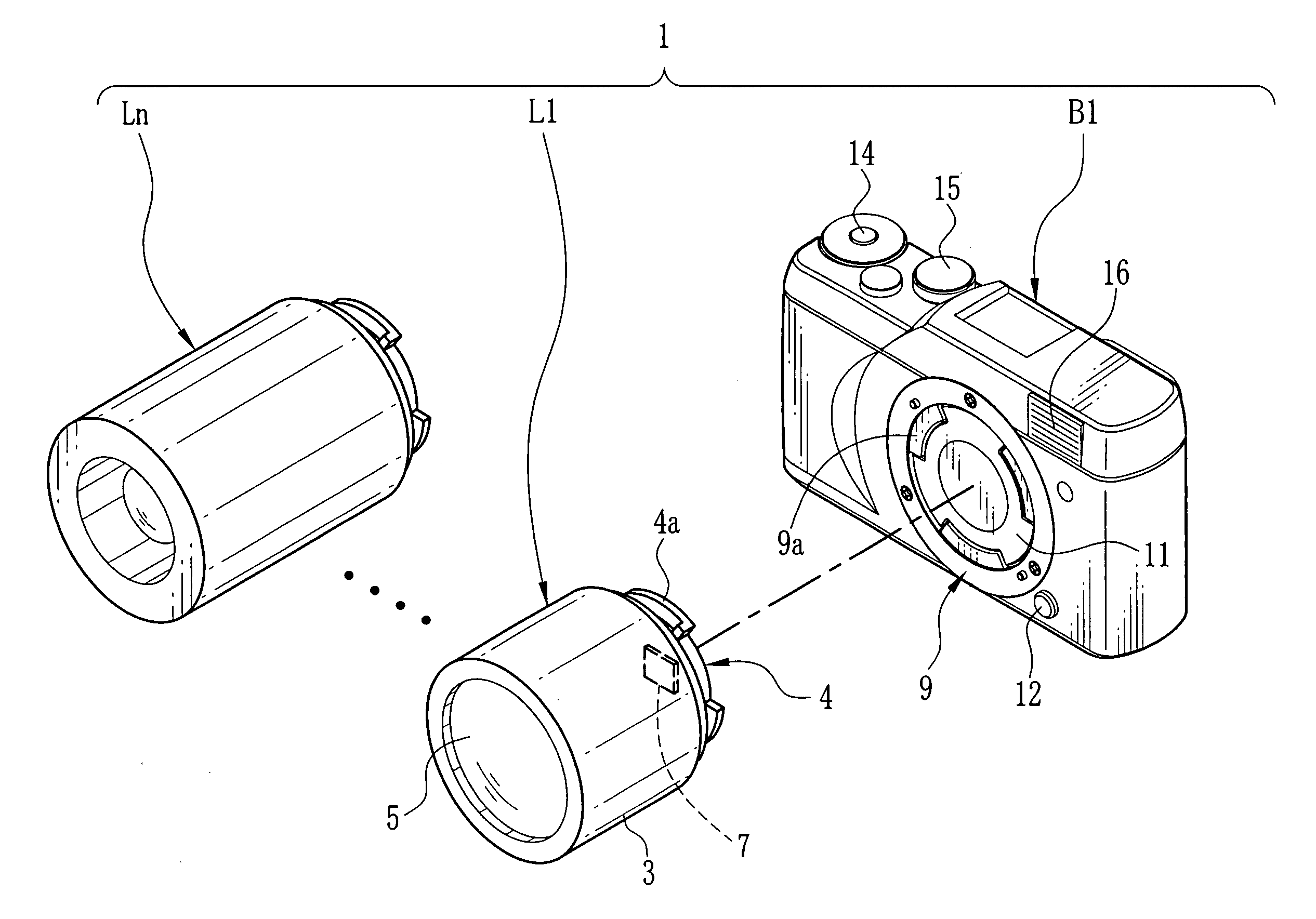
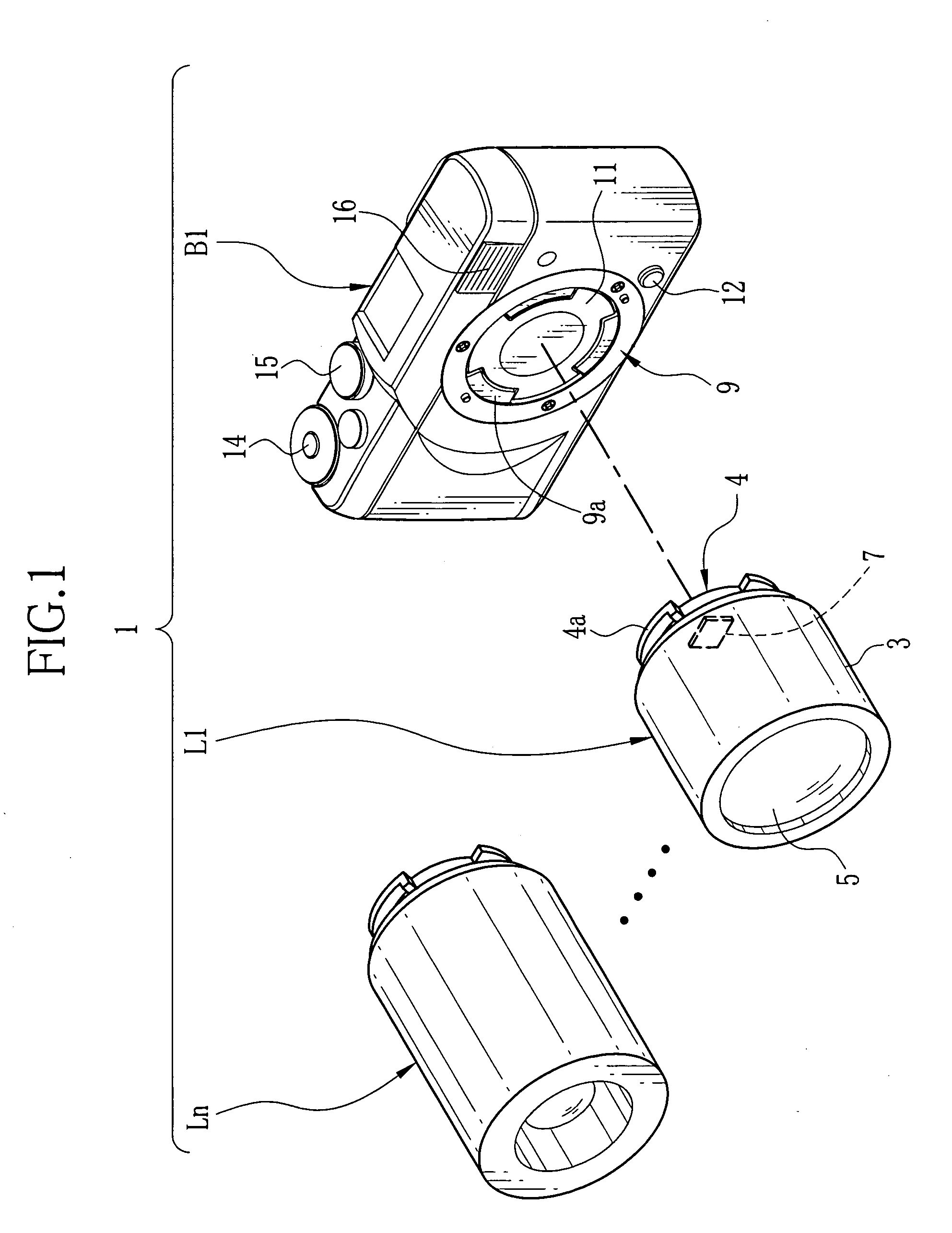
[0039] In FIG. 1, a digital camera system 1 is constituted of various types of lens units L1 to Ln (n is a natural number) with different image sensors, and a camera body B1. Each lens unit L1 to Ln has an imaging optical system and an image sensor to generate image signals. One of the lens units L1 to Ln is detachably attached to the camera body B1. The camera body B1 receives the image signals from the attached lens unit, and the received image signals are stored in a memory card and / or displayed on an LCD.

[0040] Hereinafter, an example in which the lens unit L1 is attached to the camera body B1 is described. A basic configuration is common to all the lens units L1 to Ln except for configurations of the imaging optical systems and / or CCD properties. Image data transmitted from the lens units L1 to Ln to the camera body B1 is YC data and / or RAW file compatible with the camera body B1.

[0041] The lens unit L1 includes a lens barrel section 3 and a lens-side mount section 4. The len...


PUM


Abstract

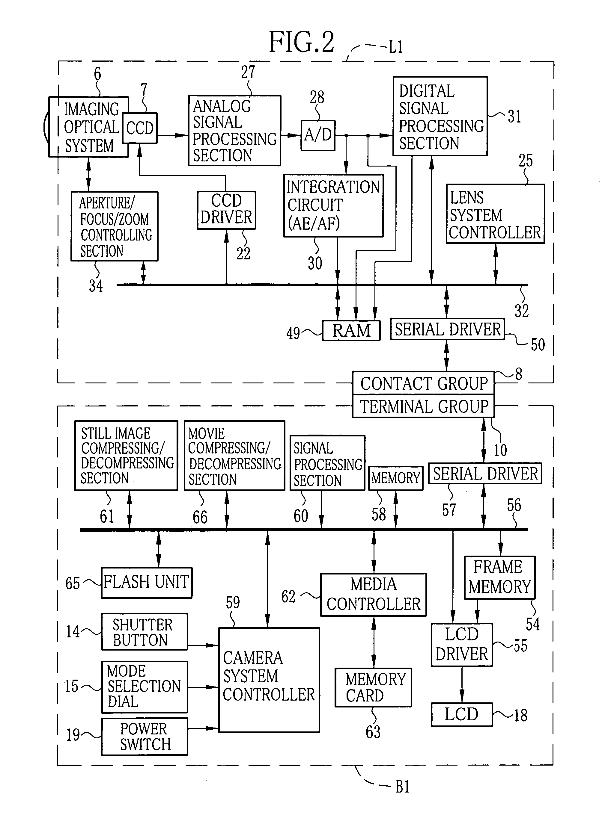
One of plural lens units is selectively attached to a camera body. An image signal output from a CCD is converted into CCD RAW data in an A / D converter, and then converted into YC data in a digital signal processing section. The YC data is sent to the camera body and written in a memory. A camera system controller reads the YC data from the memory. The YC data is resized to generate a thumbnail image. The thumbnail image, and a principal image reproduced from the entire YC data are compressed in JPEG format. The compressed data, and tag information are written in a memory card as an image file. The lens unit generates a RAW file having CCD RAW data. When the RAW file is selected, the RAW file is sent to the camera body and written in the memory card without being subjected to image processing.

Description

FIELD OF THE INVENTION [0001] The present invention relates to a digital camera system with exchangeable lens units. BACKGROUND OF THE INVENTION [0002] A digital camera system in which one of various types of lens units is selected and detachably attached to a camera body is known. For instance, Japanese Patent Laid-Open Publication No. 2000-175089 discloses a digital camera of a lens unit exchangeable type in which one of exchangeable lens units is detachably attached to a camera body. Signals are transmitted and received between the attached lens unit and the camera body via a connector. Each lens unit has a taking lens, an image sensor, and a ROM in which a control program for controlling an MPU is stored. The camera body has a relatively expensive image signal processing circuit, the MPU, recording media, and the like. The MPU receives the control program and other data unique to the attached lens unit from the ROM and an EEPROM in the attached lens unit, and controls image proc...

Claims


Application Information

Patent Timeline
Patent Type & Authority Applications(United States)
IPC IPC(8): H04N5/225
CPCH04N5/23209H04N23/663
Inventor TANAKA, HIROSHI
Owner FUJIFILM CORP
Learn More